LevelOne FNC-0104FX Manual - Page 1
LevelOne FNC-0104FX Manual
 |
View all LevelOne FNC-0104FX manuals
Add to My Manuals
Save this manual to your list of manuals |
Page 1 highlights
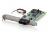
FNC-0103/0104FX Fast Ethernet 100Base-FX User's Manual (9802-Rev. D1) 1. Checklist Before you start installing the FNC-0103/0104FX, verify that the package contains the following items: FNC-0103/0104FX Board LAN Driver Diskette This User's Manual Please notify your sales representative immediately if any of the aforementioned items is missing or damaged. 2. Overview FNC-0103/0104FX is a PCI Fast Ethernet Board that fully complies with all IEEE 802.3u, 100Base-FX standards. Four LED indicators(LINK, ACT, COL and FDX) on the bracket will help to oversee the network/board link, activities, collision and full-duplex status. 3. FNC-0103/0104FX PCI Configuration For motherboards with automatic PCI configuration: No specific setup is needed You can enter the system BIOS setup menu to view or specify the interrupt line of the PCI slots For motherboards with bus master & interrupt jumpers: Enable bus master operation in a selected PCI slot and select an interrupt (IRQ) level using the appropriate motherboard jumper Enable I/O on the FNC-0103/0104FX PCI slot 4. PCI Bus System & Configuration • Ensure that the PCI machine does support master slots, INT multiple sharing and timing compatibility. Do not install FNC-0103/0104FX in PCI slave slots. Please refer to your PCI system manual and select the appropriate configuration settings. 1 • When installing multiple FNC-0103/0104FX boards at the server station, you should correctly configure the IRQ settings of the PCI slot. Up to four FNC0103/0104FX boards can be installed in a PCI file server running NetWare system. The FNC-0103/0104FX server boards share the same interrupt line with the driver supporting multiple INT services at a time. Each FNC0103/0104FX's IRQ should not conflict with that of other board. • Operation in full or half-duplex(Default) mode is configured by LAN driver options. The operating mode should match the remote link device working status. • You must use EMM386 version 4.49 or higher, and install both DOS & EMM386 that came from the same DOS package to avoid software problems. 5. Network Connection 100Base-FX/TX network allows 512-bit time delay between any two node stations in a collision domain. The Fiber/TP cable with devices' bit-time delay(round trip) are as below: 100Base-FX 100Base-TX DTE↔DTE : 100 DTE↔DTE : 100 Class II Hub: 92 Class II Hub : 92 Fiber Cable : 1.0 /m Cat. 5 TP Wire: 1.112/m DTE FX to DTE TX: 100 100Base-FX to 100Base-TX Converter: 56 The overall bit-time of Fiber/TP wires and devices must be within 512 bit in a segment. You may use Switching Hub to break up collision domain and extend the cabling distance.
-
 1
1 -
 2
2
 |
 |
