LevelOne FNC-0104FX Manual - Page 2
Diagnostic LEDs & Boot ROM, Technical Specifications
 |
View all LevelOne FNC-0104FX manuals
Add to My Manuals
Save this manual to your list of manuals |
Page 2 highlights
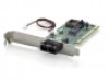
• Fiber Cable(multi-mode) Limitations: Half-duplex Class II Hub Node to Node Node to Hub Hub to Hub : 205m : 100m : 5m Half-duplex Switching Hub Full-duplex Switching Hub Node to Node Node to Hub Hub to Hub Node to Node Node to Hub Hub to Hub : 412m : 412m : 412m : 2km : 2km : 2km Connecting to Router, Bridge, or Switching Hub, please refer to the device Technical Manual. 2 6. Diagnostic LEDs & Boot ROM The Link LED lights when fiber cable connection is good and the Act LED blinks to indicate the activity. Collision and fullduplex LED report the board operating status. To add the Remote Boot feature to a workstation, insert the Boot ROM into socket as shown below. Align the notch and pins on the Boot ROM with the notch and pin receptacles on the ROM socket. Gently push the Boot ROM into the socket, being careful not to bend the pins. Fig. 1 Diagnostic LEDs and Boot ROM Socket 7. Technical Specifications • Standard : IEEE 802.3u Fast Ethernet 100Base-FX • Connector: FNC-0103FX: ST(multi-mode) connector FNC-0104FX: SC(multi-mode) connector • Cable: Fiber 50/125, 62.5/125, 100/140µm multi-mode • Data Transfer Mode / Speed: PCI bus master Full or half-duplex(Default) mode 100Mbps speed • LINK, ACT, COL, and FDX LEDs on the bracket • Power Requirement : 2.0A @+5V • Ambient Temperature : 0 to 50°C • Humidity : 5% to 90% • PCB Dimensions : 4.84"(L) × 3.15"(H) • Complies with FCC Part 15 Class A and CE Mark 3
-
 1
1 -
 2
2
 |
 |
