LevelOne GSW-2457 Manual - Page 10
Identifying External Components
 |
View all LevelOne GSW-2457 manuals
Add to My Manuals
Save this manual to your list of manuals |
Page 10 highlights
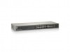
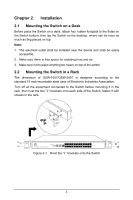
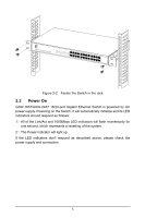
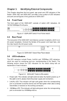
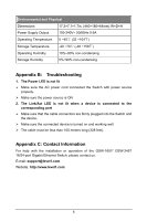
Chapter 3. Identifying External Components This Chapter describes the front panel, rear panel and LED indicators of the Switch. GSW-1657 and GSW-2457 just differ in the number of LED indicators and ports and all figures in this guide are of GSW-2457. 3.4 Front Panel The front panel of the GSW-2457 consists of switch LED indicators, 24 10/100/1000Mbps RJ-45 ports. Figure 3-1 GSW-2457 Switch Front Panel sketch 3.5 Rear Panel The rear panel of the GSW-2457 only features a power receptacle, which is an AC power receptacle. Connect the female of the power cord head here, and the male head to the AC power outlet. Figure 3-2 GSW-2457 Switch Rear Panel sketch 3.6 LED Indicators The LED indicators include Power, Link/Act and 1000Mbps LED indicators, which are used for monitoring and pre- troubleshooting of the Switch. The following section shows the LED indicators for the switch along with an explanation of each indicator. Figure 3-3 GSW-2457 Switch LEDs sketch ¾ Power LED: This indicator will light solid red when the Switch powers up. If the LED is not lit, please check the power supply and connection. ¾ Link/Act LED: This indicator will light solid green when the corresponding port is connected to another device and will flash green when data is being transmitted or received on the working connection. ¾ 1000Mbps LED: This indicator will light solid green when the corresponding port is connected to a 1000Mbps device. 6
-
 1
1 -
2
-
3
-
4
-
 5
5 -
 6
6 -
 7
7 -
 8
8 -
 9
9 -
 10
10 -
 11
11 -
 12
12
 |
 |
