LevelOne GTL-2660 Manual - Page 14
To establish a network connection, Connect the power cord
 |
View all LevelOne GTL-2660 manuals
Add to My Manuals
Save this manual to your list of manuals |
Page 14 highlights
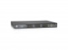
Chapter 2 Hardware Installation 4. Secure the L-shaped brackets on the guide slots (as shown in the figure below) fixed at both ends of the rack, to ensure that the switch can be mounted on the rack in a stable, horizontal manner; Figure 2-1 Rack Installation 2.4 To establish a network connection To establish network connection: Insert the appropriate media into the ports of the device to establish a connection between networks. Tip: The electrical ports of the switch can automatically detect the crossover cables, so users can either connect a network card orrouter using a straight-through network cable or using a crossover cable. 2.5 Connect the power cord The switch uses 100~240V, 50/60HZ AC power supply. Before power on, you must ensure a normal power supply, connections and grounding, as it may cause exceptions or damage to the system. The connection procedures are as following: 1. Plug one end of the switch power cord into the AC power socket on the rear panel of the switch, and the other end into the AC power socket; 2. Check that the switch's power indicator (PWR) is on, and if so, it indicates that the power supply is connected properly. After connecting the power supply, the switch enters into the self-test stage. In this process, the LED description as shown in Table 1-2 can be referred to judge if the system runs normally or not. http://www.level1.com Page 8
-
 1
1 -
2
-
3
-
4
-
5
-
6
-
7
-
8
-
 9
9 -
 10
10 -
 11
11 -
 12
12 -
 13
13 -
 14
14 -
 15
15 -
 16
16 -
 17
17 -
 18
18 -
 19
19 -
20
-
21
-
22
-
23
-
24
-
25
-
26
-
27
-
28
-
29
-
30
-
31
-
32
-
33
-
34
-
35
-
36
-
37
-
38
-
39
-
40
-
41
-
42
-
43
-
44
-
45
-
46
-
47
-
48
-
49
-
50
 |
 |
