LevelOne GVS-3800 Manual - Page 29
Application 1 description, Application 1 Scenario explain, Purpose, How to setting on Converter A &
 |
View all LevelOne GVS-3800 manuals
Add to My Manuals
Save this manual to your list of manuals |
Page 29 highlights
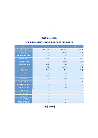
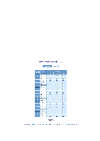
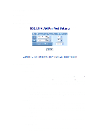
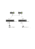
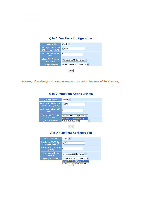
Ingress Filter: Enable or Disable VLAN ingress filter. Application 1 description: Example for Replace Vlan description: Topology: Converter A Converter B Fig. 3-11-1 Application 1 Scenario explain: Switch A VLAN setting: Port 1 ~ 4: members of VLAN 2 group (PVID: 2) Port 1 is trunk mode, port 2~4 is access mode. Switch B VLAN setting: Port 5 ~ 8: members of VLAN 10 group (PVID: 10) Port 5 is trunk mode .port 6~8 is access mode. Purpose: Client A & B can communicate with each other (and don't changed original setting on Switch A & B) How to setting on Converter A & B? Step1. Pls add VLAN 2 & 10 entry on the table, and confirm port members are selected. (The same VLAN group setting on Converter A & B) 23
-
 1
1 -
2
-
3
-
4
-
5
-
6
-
7
-
8
-
9
-
10
-
11
-
12
-
13
-
14
-
15
-
16
-
17
-
18
-
19
-
20
-
21
-
22
-
23
-
 24
24 -
 25
25 -
 26
26 -
 27
27 -
 28
28 -
 29
29 -
 30
30 -
 31
31 -
 32
32 -
 33
33 -
 34
34 -
35
-
36
-
37
-
38
-
39
-
40
-
41
-
42
-
43
-
44
-
45
-
46
-
47
-
48
 |
 |

23
Ingress Filter:
Enable or Disable VLAN ingress filter.
Application 1 description:
Example for Replace Vlan description:
Topology:
Application 1 Scenario explain:
Switch A VLAN setting:
Port 1 ~ 4: members of VLAN 2 group (PVID: 2)
Port 1 is trunk mode, port 2~4 is access mode.
Switch B VLAN setting:
Port 5 ~ 8: members of VLAN 10 group (PVID: 10)
Port 5 is trunk mode .port 6~8 is access mode.
Purpose:
Client A & B can communicate with each other (and don’t changed
original setting on Switch A & B)
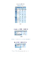
How to setting on Converter A & B?
Step1.
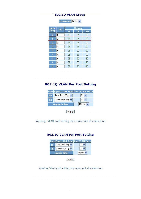
Pls add VLAN 2 & 10 entry on the table, and confirm port members are
selected.
(The same VLAN group setting on Converter A & B)
Fig. 3-11-1
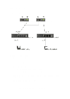
Converter A
Converter B