LevelOne IES-0920 Quick Install Guide - Page 2
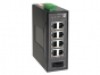
Power Input, DIP Switch, DIN Rail Mount, 100Base-TX Connector
 |
View all LevelOne IES-0920 manuals
Add to My Manuals
Save this manual to your list of manuals |
Page 2 highlights
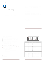
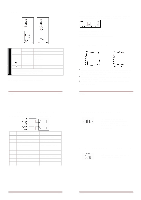
Power Input Terminal Block + 10 - 48VDC PW1 - Power Ground + 10 - 48VDC PW2 - Power Ground Earth Ground Relay Output 1A @ 24VDC 1. The relay contact opens if Power1 or Power2 falls 2. The relay contact opens if the Port Link is broken (When Link Down Detection is enabled) Note: 12VDC DC Jack Input type is optional IES-0920 Page 4 10/100Base-TX Connector The following lists the pin-out of 10/100Base-TX ports. Pin Standard Port 1 Output Transmit Data + 2 Output Transmit Data 3 Input Receive Data + 4 NC 5 NC 6 Input Receive Data 7 NC 8 NC Uplink Port Input Receive Data + Input Receive Data Output Transmit Data + NC NC Output Transmit Data NC NC DIP Switch This DIP Switch features the Port Fault Detection; once enabled, it sends fault signal (relay opens) when the port link is broken On: Enable Port Fault Detection Off: Disable Port Fault Detection Note: Pin No. maps to Port No & extra Pin has no function DIN Rail Mount Assembly: Place the switch on the DIN rail from above using the slot. Push the front of the switch toward the mounting surface until it audibly snaps into place Start-up: Connect the supply voltage to start up the switch via the terminal block (or DC JACK) Dismantling: Pull out the lower edge and then remove the switch from the DIN rail. IES-0920 Page 5 100Base-FX Connection The Tx (transmit) port of device I is connected to the Rx (receive) port of device II, and the Rx (receive) port of device I to the Tx (transmit) port of device II. WDM 100Base-BX Connection Only one optical fiber is required to transmit and receive data IES-0920 Page 6 IES-0920 Page 7
-
 1
1 -
 2
2
 |
 |
