LevelOne KVM-0831 Manual - Page 17
Operate and Display, Display Example - level
 |
View all LevelOne KVM-0831 manuals
Add to My Manuals
Save this manual to your list of manuals |
Page 17 highlights
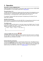
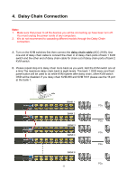
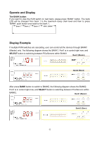
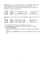
Operate and Display The BANK button: If you want to view the KVM switch on next bank, please press "BANK" button. The bank LED will be changed from bank 1 to the maximum daisy chain level and then to press "BANK" push button once back to the bank 1. Bank 1 Bank 2 Bank 3 MAX. BANK Display Example If multiple KVM switches are cascading, user can control all the devices through BANK1 (Master) only. The following diagram shows the BANK1, Port1 is in control right now, and SELECT button is switching between PCs/Servers within BANK1. Bank1 (Master) Bank2 (Slave) After press BANK button to switch to BANK2, the following diagram shows the BANK2, Port1 is in control right now, and SELECT button is switching between PCs/Servers within BANK2. Bank1 (Master) Bank2 (Slave) 12
-
 1
1 -
2
-
3
-
4
-
5
-
6
-
7
-
8
-
9
-
10
-
11
-
 12
12 -
 13
13 -
 14
14 -
 15
15 -
 16
16 -
 17
17 -
 18
18 -
 19
19 -
 20
20 -
 21
21 -
 22
22 -
23
-
24
-
25
-
26
-
27
-
28
-
29
-
30
-
31
 |
 |
