Lexmark T632dtn Service Manual - Page 91
Paper Jam displays, paper jammed over the Pass Thru Sensor., Paper Low displays when tray
 |
UPC - 734646538404
View all Lexmark T632dtn manuals
Add to My Manuals
Save this manual to your list of manuals |
Page 91 highlights
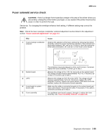
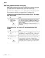
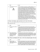
4060-xxx FRU 4 High-capacity feeder option control board Action Check the voltage on J8-1 (green). The voltage measures +24 V dc. If incorrect, check the autoconnect system for any problems. +24 V dc must come from the base printer through the autoconnect system to the high-capacity input for the high-capacity feeder to be recognized. If the voltage is correct, check the voltages at J11-3(red) and J11-4(red). The voltages measure +24 V dc. If correct, replace the high-capacity feeder option system board. If incorrect, disconnect J8 from the system board and measure the voltages again. If incorrect, check the LVPS cable and the AC internal wiring from the input appliance receptacle. If incorrect, replace as necessary. If correct, replace the LVPS. If the voltages are correct, check the stepper motor for shorts from the motor housing to each pin on the motor connector. If you find a short between any pin and the motor housing, replace the motor assembly. If no shorts are found, replace the high-capacity feeder option control board. Check the voltage at J9-1 (light blue). The voltage measures approximately +24 V dc. If incorrect, disconnect the cable at J9 and check the voltage again. If the voltage continues to be incorrect, replace the high-capacity feeder option system board. If the voltage measures correctly, check the cable. If the cable is damaged, replace as necessary. If no problem is found with the cable, replace the highcapacity feeder option control board. 24x Paper Jam displays, paper jammed over the Pass Thru Sensor. Where x=the printer displays the value of x for the paper tray where the error occurs. For example: 242 is a Paper Jam Tray 2 FRU 1 Pass thru sensor and flag assembly 2 Power takeoff shaft and spring, bevel gear, feed roll gear, drive roll assembly, wear plate, drive shaft bearings, and skewed backup roller Action The tray x option system board did not detect a piece of paper actuating the pass thru sensor. Remove any jammed sheets of paper from the printer and check the pass thru sensor and flag for proper operation by running the appropriate Tray Sensor Test from the diagnostics menu. If the test fails, check the sensor for correct installation and the flag for proper operation. Also check the sensor cable to make sure it is correctly connected to the option system board. If incorrect, replace the tray x option pass thru sensor assembly. Check these parts for signs of broken or damaged parts, contamination on the drive rollers or wear plate and wear or damage to the drive shaft bearings. Check the drive roll assembly and skewed backup roller for wear, slick spots, material buildup, and oil or grease on the rollers. Also check for proper operation of the paper aligning assembly. Repair or replace parts as necessary. Tray x Paper Low displays when tray x is full or has adequate paper in the tray. FRU 1 Paper low switch Paper low switch cable High-capacity feeder Input system board Action Run the sensor diagnostics for tray x (x=the number that represents the high-capacity input tray). If the test fails, disconnect the paper low switch cable from J3 on the high-capacity system board. Short pins 1 and 2 together while observing the sensor test on the display. If the display does not change, replace the high-capacity feeder system board. If the display changes check the continuity of the switch. If incorrect, replace the switch. If correct, replace the switch cable. Diagnostic information 2-57
-
 1
1 -
2
-
3
-
4
-
5
-
6
-
7
-
8
-
9
-
10
-
11
-
12
-
13
-
14
-
15
-
16
-
17
-
18
-
19
-
20
-
21
-
22
-
23
-
24
-
25
-
26
-
27
-
28
-
29
-
30
-
31
-
32
-
33
-
34
-
35
-
36
-
37
-
38
-
39
-
40
-
41
-
42
-
43
-
44
-
45
-
46
-
47
-
48
-
49
-
50
-
51
-
52
-
53
-
54
-
55
-
56
-
57
-
58
-
59
-
60
-
61
-
62
-
63
-
64
-
65
-
66
-
67
-
68
-
69
-
70
-
71
-
72
-
73
-
74
-
75
-
76
-
77
-
78
-
79
-
80
-
81
-
82
-
83
-
84
-
85
-
 86
86 -
 87
87 -
 88
88 -
 89
89 -
 90
90 -
 91
91 -
 92
92 -
 93
93 -
 94
94 -
 95
95 -
 96
96 -
97
-
98
-
99
-
100
-
101
-
102
-
103
-
104
-
105
-
106
-
107
-
108
-
109
-
110
-
111
-
112
-
113
-
114
-
115
-
116
-
117
-
118
-
119
-
120
-
121
-
122
-
123
-
124
-
125
-
126
-
127
-
128
-
129
-
130
-
131
-
132
-
133
-
134
-
135
-
136
-
137
-
138
-
139
-
140
-
141
-
142
-
143
-
144
-
145
-
146
-
147
-
148
-
149
-
150
-
151
-
152
-
153
-
154
-
155
-
156
-
157
-
158
-
159
-
160
-
161
-
162
-
163
-
164
-
165
-
166
-
167
-
168
-
169
-
170
-
171
-
172
-
173
-
174
-
175
-
176
-
177
-
178
-
179
-
180
-
181
-
182
-
183
-
184
-
185
-
186
-
187
-
188
-
189
-
190
-
191
-
192
-
193
-
194
-
195
-
196
-
197
-
198
-
199
-
200
-
201
-
202
-
203
-
204
-
205
-
206
-
207
-
208
-
209
-
210
-
211
-
212
-
213
-
214
-
215
-
216
-
217
-
218
-
219
-
220
-
221
-
222
-
223
-
224
-
225
-
226
-
227
-
228
-
229
-
230
-
231
-
232
-
233
-
234
-
235
-
236
-
237
-
238
-
239
-
240
-
241
-
242
-
243
-
244
-
245
-
246
-
247
-
248
-
249
-
250
-
251
-
252
-
253
-
254
-
255
-
256
-
257
-
258
-
259
-
260
-
261
-
262
-
263
-
264
-
265
-
266
-
267
-
268
-
269
-
270
-
271
-
272
-
273
-
274
-
275
-
276
-
277
-
278
-
279
-
280
-
281
-
282
-
283
-
284
-
285
-
286
-
287
-
288
-
289
-
290
-
291
-
292
-
293
-
294
-
295
-
296
-
297
-
298
-
299
-
300
-
301
-
302
-
303
-
304
-
305
-
306
-
307
-
308
-
309
-
310
-
311
-
312
-
313
-
314
-
315
-
316
-
317
-
318
-
319
-
320
-
321
-
322
-
323
-
324
-
325
-
326
-
327
-
328
-
329
-
330
-
331
-
332
-
333
-
334
-
335
-
336
-
337
-
338
-
339
-
340
-
341
-
342
-
343
-
344
-
345
 |
 |