Lexmark XS795 Printer Languages and Interfaces Technical Reference - Page 135
Lexmark XS795 Manual
 |
View all Lexmark XS795 manuals
Add to My Manuals
Save this manual to your list of manuals |
Page 135 highlights
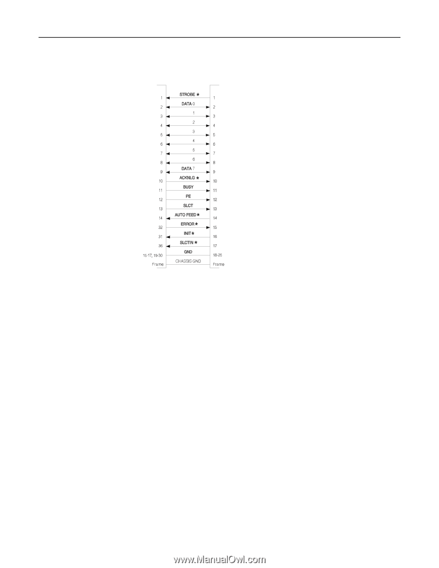
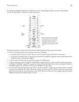
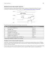
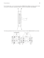
Printer interfaces 135 The following illustration shows the pin assignments for connecting the 25-pin connector to the 36-pin connector. The symbol * indicates an active low signal. Printer Side Computer Side 36-Pin Connector 1284-B 25-Pin Connector Note: Lexmark IEEE 1284 compliant cables are supported up to 20 feet. Cable lengths greater than 20 feet are not supported. The cable drawing to the left is a functional representation of the Lexmark cables; it does not reflect correct pairing of leads or unused pairs. The parallel interface consists of an 8-bit parallel data bus with the following characteristics: • Uses 17 of the 36 positions on the printer connector, as follows: - The host system controls 12 lines, which it uses to send data and commands to the printer. - The printer controls five lines. The printer uses two lines to notify the computer of successful data transfer, and three lines to report printer status. • Controls synchronization with an externally supplied STROBE* pulse. • Controls data flow control with BUSY and ACKNLG* signals. Does not carry out data transfer by ignoring the BUSY or ACKNLG* signal. (The system can carry out data transfer to the printer only when the level of the BUSY signal is low and after confirming the ACKNLG* signal is high.) • Uses standard transistor-transistor logic (TTL) levels for all interface control signals and input data. Interface conditions are based on TTL levels. All printer outputs are totem-pole TTL devices. All printer input/output (I/O) are devices with an internal pull-up resistor to 5 V. Rise and fall times of each signal must be less than 1,500 nanoseconds (ns) without slope reversal.
-
 1
1 -
2
-
3
-
4
-
5
-
6
-
7
-
8
-
9
-
10
-
11
-
12
-
13
-
14
-
15
-
16
-
17
-
18
-
19
-
20
-
21
-
22
-
23
-
24
-
25
-
26
-
27
-
28
-
29
-
30
-
31
-
32
-
33
-
34
-
35
-
36
-
37
-
38
-
39
-
40
-
41
-
42
-
43
-
44
-
45
-
46
-
47
-
48
-
49
-
50
-
51
-
52
-
53
-
54
-
55
-
56
-
57
-
58
-
59
-
60
-
61
-
62
-
63
-
64
-
65
-
66
-
67
-
68
-
69
-
70
-
71
-
72
-
73
-
74
-
75
-
76
-
77
-
78
-
79
-
80
-
81
-
82
-
83
-
84
-
85
-
86
-
87
-
88
-
89
-
90
-
91
-
92
-
93
-
94
-
95
-
96
-
97
-
98
-
99
-
100
-
101
-
102
-
103
-
104
-
105
-
106
-
107
-
108
-
109
-
110
-
111
-
112
-
113
-
114
-
115
-
116
-
117
-
118
-
119
-
120
-
121
-
122
-
123
-
124
-
125
-
126
-
127
-
128
-
129
-
 130
130 -
 131
131 -
 132
132 -
 133
133 -
 134
134 -
 135
135 -
 136
136 -
 137
137 -
 138
138 -
 139
139 -
 140
140 -
141
-
142
-
143
-
144
-
145
-
146
-
147
-
148
 |
 |