LiftMaster 1355 1355 Manual - Page 17
Installation Step 5
 |
View all LiftMaster 1355 manuals
Add to My Manuals
Save this manual to your list of manuals |
Page 17 highlights
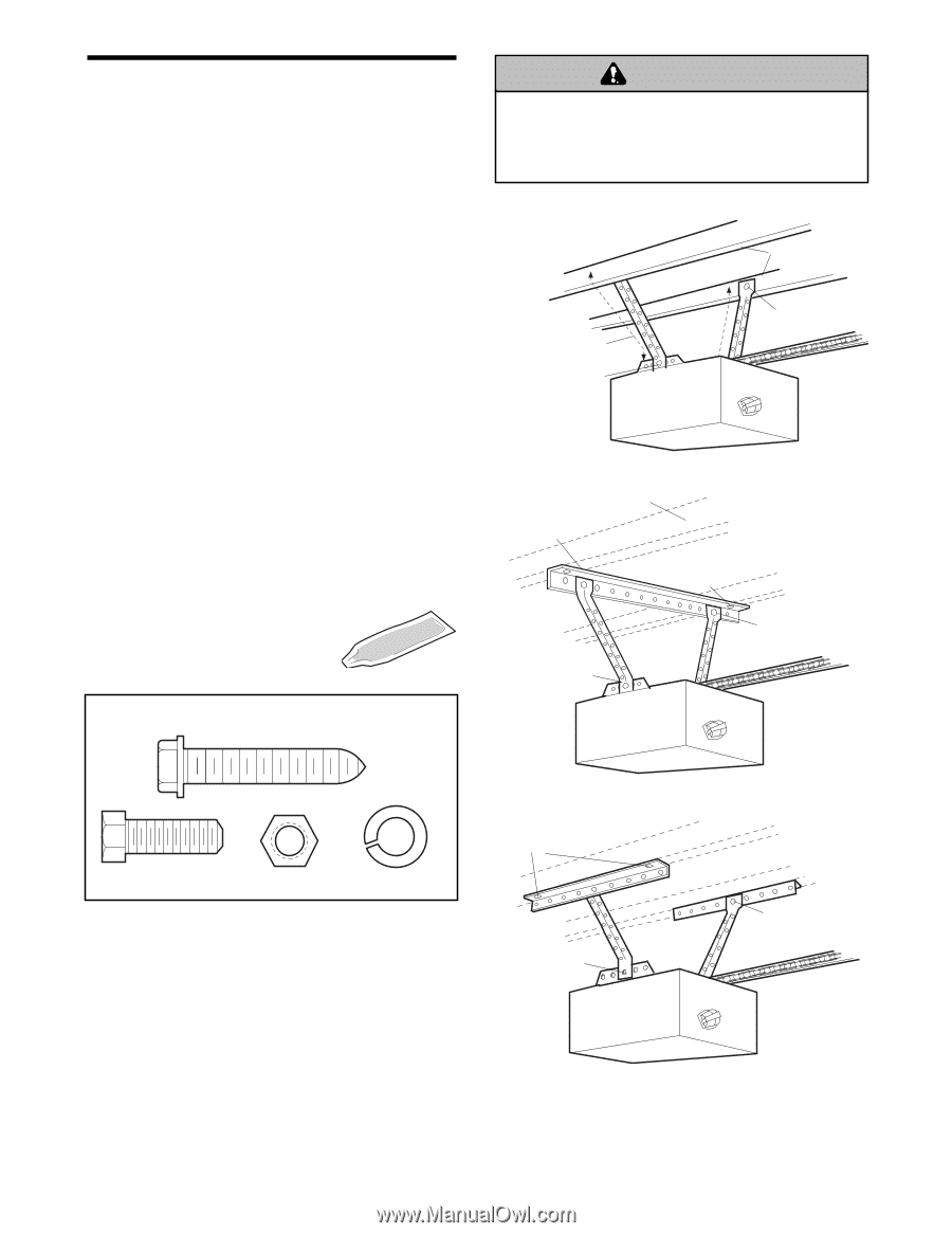
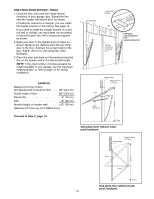
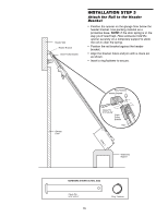
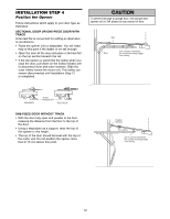
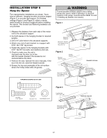
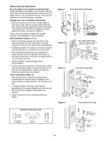
INSTALLATION STEP 5 Hang the Opener Two representative installations are shown. Yours may be different. Hanging brackets should be angled (Figure 1) to provide rigid support. On finished ceilings (Figure 2 and Figure 3), attach a sturdy metal bracket to structural supports before installing the opener. This bracket and fastening hardware are not provided. 1. Measure the distance from each side of the motor unit to the structural support. 2. Cut both pieces of the hanging bracket to required lengths. 3. Drill 3/16" pilot holes in the structural supports. 4. Attach one end of each bracket to a support with 5/16"-18x1-7/8" lag screws. 5. Fasten the opener to the hanging brackets with 5/16"-18x7/8" hex bolts, lock washers and nuts. 6. Check to make sure the rail is centered over the door (or in line with the header bracket if the bracket is not centered above the door). 7. Remove the 2x4. Operate the door manually. If the door hits the rail, raise the header bracket. 8. Grease the top and underside of the rail surface where the trolley slides with rail grease. HARDWARE SHOWN ACTUAL SIZE WARNING To avoid possible SERIOUS INJURY from a falling CAUTION garage door opener, fasten it SECURELY to structural supports of the garage. Concrete anchors MUST be used if installing any brackets into masonry. Figure 1 Structural Supports Measure Distance Bolt 5/16"-18x7/8" Lock Washer 5/16" Nut 5/16"-18 Lag Screws 5/16"-18x1-7/8" Figure 2 Bracket (Not Provided) Hidden Support Lag Screws 5/16"-18x1-7/8" FINISHED CEILING Bolt 5/16"-18x7/8" Lock Washer 5/16" Nut 5/16"-18 (Not Provided) Bolt 5/16"-18x7/8" Lock Washer 5/16" Nut 5/16"-18 Lag Screw 5/16"-9x1-5/8" Hex Bolt 5/16"-18x7/8" Nut 5/16"-18 Lock Washer 5/16" Figure 3 Lag Screws 5/16"-18x1-7/8" Bolt 5/16"-18x7/8" Lock Washer 5/16" Nut 5/16"-18 FINISHED CEILING (Not Provided) Bolt 5/16"-18x7/8" Lock Washer 5/16" Nut 5/16"-18 17
-
 1
1 -
2
-
3
-
4
-
5
-
6
-
7
-
8
-
9
-
10
-
11
-
 12
12 -
 13
13 -
 14
14 -
 15
15 -
 16
16 -
 17
17 -
 18
18 -
 19
19 -
 20
20 -
 21
21 -
 22
22 -
23
-
24
-
25
-
26
-
27
-
28
-
29
-
30
-
31
-
32
-
33
-
34
-
35
-
36
-
37
-
38
-
39
-
40
 |
 |