LiftMaster CAPXM Installation Manual - English French Spanish Manufactured Pri - Page 17
Access Control, Gate Access (wired), Door 1 Or 2, Request To Exit, Wiegand, Status, Primary Relay
 |
View all LiftMaster CAPXM manuals
Add to My Manuals
Save this manual to your list of manuals |
Page 17 highlights
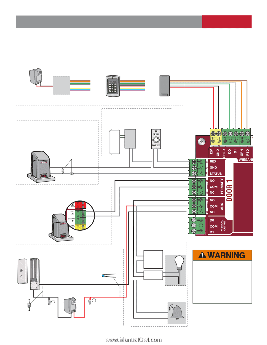
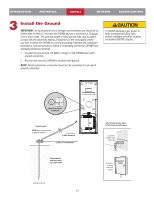
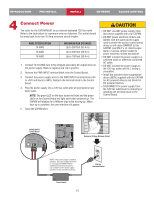
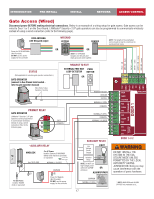
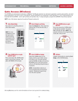
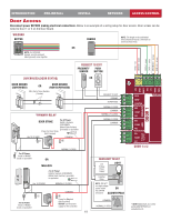
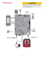
INTRODUCTION PRE-INSTALL INSTALL NETWORK ACCESS CONTROL Gate Access (Wired) Disconnect power BEFORE making electrical connections. Below is an example of a wiring setup for gate access. Gate access can be wired to Door 1 or 2 on the Door Board. LiftMaster® Security+ 2.0® gate operators can also be programmed to communicate wirelessly instead of using a wired connection (refer to the following page). RFID ANTENNA with Wiegand output Power for RFID ANTENNA (Not Provided) DO NOT use the power supply for the controller WIEGAND KEYPAD READER OR OR NOTE: For KPR2000 keypad, wire the pink and black (ground) wires together. NOTE: The length of the unshielded wires should be kept to a minimum to avoid electrical noise. 12Vdc - red GROUND - black DATA 0 - green DATA 1 - white GREEN LED - orange RED LED - brown STATUS (Not applicable for wireless gate operator connections.) GATE OPERATOR (connect to Aux Closed Limit switch refer to gate operator manual) EOL (End of Line) Resistor (1k ohm) PRIMARY RELAY GATE OPERATOR LiftMaster® Security+ 2.0® gate operators can be programmed to communicate wirelessly instead of using a wired connection. Refer to the following page. REQUEST TO EXIT EXTERNAL FREE EXIT PUSH LOOP DETECTOR BUTTON OR EXIT COMMON REQUEST TO EXIT GROUND STATUS NORMALLY OPEN COMMON NORMALLY OPEN COMMON NORMALLY CLOSED *AUXILIARY RELAY MAGLOCK Use 18-22 AWG For AC Power: Install a Siemens S10K30MOV (Metal Oxide Varistor) (provided) or equivalent NORMALLY CLOSED For DC Power: Install a 1N4005 diode or equivalent - COMMON + Power for Maglock (Not Provided) DO NOT use the power supply for the controller AUXILIARY RELAY Low Voltage Power Supply Isolation Relay LIGHT LOAD LINE NEUTRAL NOTE: DO NOT run high voltage power within the CAPXM OR enclosure. ALARM BYPASS COMMON NORMALLY OPEN 17 DOOR 1 or 2 DO NOT INSTALL THE SYSTEM IN THE FAIL SECURE MODE UNLESS PERMITTED BY THE LOCAL AUTHORITY HAVING JURISDICTION. Doing so may cause interference with the operation of panic hardware. * NOTE: MAGLOCK and ALARM BYPASS not evaluated by UL.
-
 1
1 -
2
-
3
-
4
-
5
-
6
-
7
-
8
-
9
-
10
-
11
-
 12
12 -
 13
13 -
 14
14 -
 15
15 -
 16
16 -
 17
17 -
 18
18 -
 19
19 -
 20
20 -
 21
21 -
 22
22 -
23
-
24
-
25
-
26
-
27
-
28
-
29
-
30
-
31
-
32
-
33
-
34
-
35
-
36
-
37
-
38
-
39
-
40
-
41
-
42
-
43
-
44
-
45
-
46
-
47
-
48
-
49
-
50
-
51
-
52
-
53
-
54
-
55
-
56
-
57
-
58
-
59
-
60
-
61
-
62
-
63
-
64
-
65
-
66
-
67
-
68
-
69
-
70
-
71
-
72
-
73
-
74
-
75
-
76
-
77
-
78
-
79
-
80
 |
 |