LiftMaster CAPXM Installation Manual - English French Spanish Manufactured Pri - Page 19
Door Access, Request To Exit, Supervised Door Status, Primary Relay, Auxiliary Relay, Wiegand
 |
View all LiftMaster CAPXM manuals
Add to My Manuals
Save this manual to your list of manuals |
Page 19 highlights
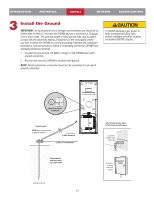
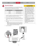
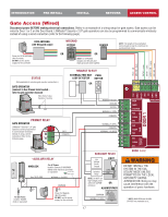
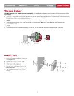
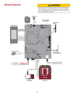
INTRODUCTION PRE-INSTALL INSTALL NETWORK ACCESS CONTROL Door Access Disconnect power BEFORE making electrical connections. Below is an example of a wiring setup for door access. Door access can be wired to Door 1 or 2 on the Door Board. WIEGAND KEYPAD READER NOTE: The length of the unshielded wires should be kept to a minimum to avoid electrical noise. OR NOTE: For KPR2000 keypad, wire the pink and black (ground) wires together. 12Vdc - red GROUND - black DATA 0 - green DATA 1 - white GREEN LED - orange RED LED - brown REQUEST TO EXIT PROXIMITY PUSH SENSOR BUTTON SUPERVISED (DOOR STATUS) DOOR SENSOR (SUPERVISED) OR DOOR SENSOR (NON-SUPERVISED) EOL (End of Line) Resistor (1k ohm) *PRIMARY RELAY DOOR STRIKE For AC Power: Install a Siemens S10K30MOV (Metal Oxide Varistor) (provided) or equivalent Power for Door Strike (Not Provided) Use 18-22 AWG COMMON + OR REQUEST TO EXIT GROUND SUPERVISED NORMALLY OPEN COMMON NORMALLY CLOSED NORMALLY OPEN COMMON - - NORMALLY OPEN For DC Power: Install a 1N4005 diode or equivalent OR MAGLOCK For AC Power: Install a Siemens S10K30MOV (Metal Oxide Varistor) (provided) or equivalent Use 18-22 AWG NORMALLY CLOSED For DC Power: Install a 1N4005 diode or equivalent COMMON + Power for Maglock (Not Provided) DO NOT use the power supply for the controller 19 AUXILIARY RELAY Low Voltage Power Supply LIGHT Isolation Relay LOAD LINE NEUTRAL NOTE: DO NOT run high voltage power within OR the CAPXM enclosure. ALARM BYPASS COMMON NORMALLY OPEN DOOR 1 or 2 * NOTE: MAGLOCK, door strike and ALARM BYPASS not evaluated by UL.
-
 1
1 -
2
-
3
-
4
-
5
-
6
-
7
-
8
-
9
-
10
-
11
-
12
-
13
-
 14
14 -
 15
15 -
 16
16 -
 17
17 -
 18
18 -
 19
19 -
 20
20 -
 21
21 -
 22
22 -
 23
23 -
 24
24 -
25
-
26
-
27
-
28
-
29
-
30
-
31
-
32
-
33
-
34
-
35
-
36
-
37
-
38
-
39
-
40
-
41
-
42
-
43
-
44
-
45
-
46
-
47
-
48
-
49
-
50
-
51
-
52
-
53
-
54
-
55
-
56
-
57
-
58
-
59
-
60
-
61
-
62
-
63
-
64
-
65
-
66
-
67
-
68
-
69
-
70
-
71
-
72
-
73
-
74
-
75
-
76
-
77
-
78
-
79
-
80
 |
 |
