LiftMaster CSL24V CSL24V Quick Start Guide Manual - Page 2
Wiring, Initial Limits And Force Adjustment, Fine Tune The Force, Obstruction Test - gate operator
 |
View all LiftMaster CSL24V manuals
Add to My Manuals
Save this manual to your list of manuals |
Page 2 highlights
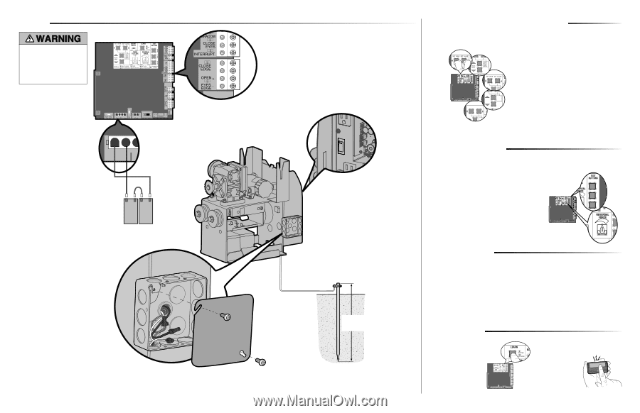
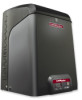
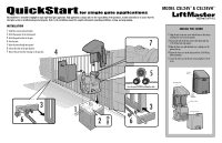
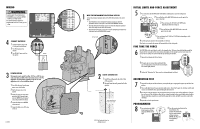
WIRING To protect against fire and electrocution: • DISCONNECT power and battery BEFORE installing or servicing operator. For continued protection against fire: • Replace ONLY with fuse of same type and rating. 4 CONNECT BATTERIES 1 Connect the battery wires to the J15 plug on the control board. 2 Turn ON AC power to the operator. 3 Turn ON the AC power switch on the operator. RESET ALARM + - + BATT DC Red Wire Jumper 3 POWER WIRING This operator can be wired for either 120 Vac or 240 Vac or a solar panel (not provided). These instructions show a 120 Vac application. For information regarding a 240 Vac or solar application refer to the installation manual. 1 Turn off the AC power from the main power source circuit breaker. 2 Run the AC power wires to the operator. 3 Connect the green wire to the earth ground rod and AC ground using a wire nut. NOTE: The earth ground rod can be grounded to the chassis. 4 Connect the white wire to NEUTRAL using a wire nut. 5 Connect the black wire to HOT using a wire nut. Junction Box 01-35590 OPEN CLOSE STOP Black Wire 1 WIRE THE ENTRAPMENT PROTECTION DEVICES Connect the entrapment protection device to the EYES EDGE terminal on the control board. • Close Photoelectric Sensor Entrapment Protection: Connect wires from the photoelectric sensors to the Inputs on the CLOSE EYES/INTERRUPT terminal. • Close Edge Entrapment Protection: Connect wires from the entrapment protection device to the Inputs on the CLOSE EDGE terminal. • Open Entrapment Protection: Connect wires from the entrapment protection device to the Inputs on the OPEN EYES/EDGE terminal. AC Power Switch 2 EARTH GROUND ROD 1 Install the earth ground rod within 3 feet of the operator. 2 Run wire from the earth ground rod to the operator. Check national and local codes for proper depth ©2011 The Chamberlain Group, Inc. All Rights Reserved INITIAL LIMITS AND FORCE ADJUSTMENT 5 1 Press and release the SET OPEN and SET CLOSE buttons simultaneously to enter limit setting mode. 2 Press and hold one of the MOVE GATE buttons to move the gate to the open or close limit. PRESS & RELEASE TO BEGIN 3 Press and release the SET CLOSE or SET OPEN button depending on which limit is being set. TO BEGIN LIMIT 4 Press and hold one of the MOVE GATE button to move the RESET ALARM MOVE PRESS & RELEASE TO BEGIN LIMIT SETUP gate to the other limit. GATE 5 SET OPEN SET CLOSE INPUT POWER STATUS: OFF 5 Press and release the SET CLOSE or SET OPEN button depending on which PRESS & RELEASE TO BEGIN LIMIT limit is being set. 6 Cycle the gate open and close. This automatically sets the force. When limits are set properly the operator will automatically exit limit setting mode. FINE TUNE THE FORCE 6 The FORCE DIAL on the control board is used for fine tuning the force. The force setting should be high enough that the gate will not reverse by itself nor cause nuisance interruptions, but low enough to prevent serious injury to a person. The force setting is the same for both the open and close gate directions. 1 Open and close the gate with the test buttons. XMITTER NETWORK 2 If the gate stops or reverses before reaching the fully open or closed position, increase the force by turning the force control slightly clockwise. NETWORK RESET ALARM 3 Perform the "Obstruction Test" after every force setting adjustment (see below). 60 180 MIN MAX BATT LOW OBSTRUCTION TEST 7 1 Open and close the gate with the test buttons, ensuring that the gate is stopping at the proper open and close limit positions. 2 Place a solid object between the open gate and a rigid structure. Ensure that the gate, the solid object, and the rigid structure can withstand the forces generated during this obstruction test. 3 Run the gate in the close direction. The gate should stop and reverse upon contact with the solid object. If the gate does not reverse off the solid object, reduce the force setting by turning the force control slightly counter-clockwise. The gate should have enough force to reach both the open and close limits, but MUST reverse after contact with a solid object. 4 Repeat the test for the open direction. PROGRAMMING 8 1 Press and release the LEARN button (operator will beep and green XMITTER LED will light). 2 Press the remote control button for the desired function. The operator will automatically exit learn mode (operator will beep and green XMITTER LED will go out) if programming is successful.
-
 1
1 -
 2
2
 |
 |