LiftMaster Dial Code Dial Code Controller Manual - Page 28
PARTS LIST AND DIAGRAM, LC Processor - international
 |
View all LiftMaster Dial Code manuals
Add to My Manuals
Save this manual to your list of manuals |
Page 28 highlights
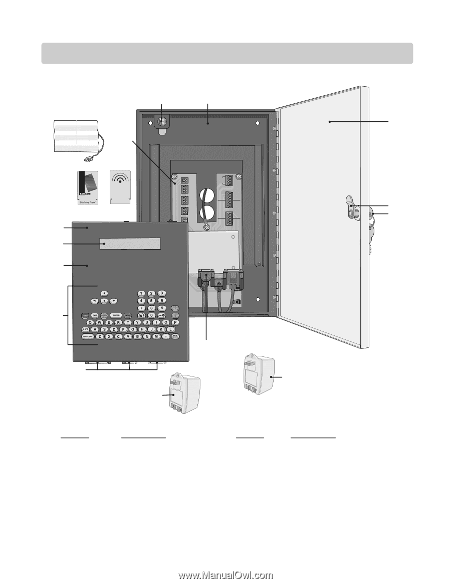
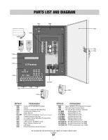
PARTS LIST AND DIAGRAM T010 T009 T011 T060 T020 T030 Memory Card Remo e Access RS-485 COMMUNICATOR CARD capacity Elite Entry Phone RS-485 Card T027 LC Processor TEL LINE RS 485 (1) RS 485 (2) RS 485 (3) 5 (4) TIP R NG (+) () GND (+) () GND (+) () GND (+) () GND 12V AC/DC POWER NPUT DOOR NO DOOR NC DOOR C GATE NO GATE NC GATE C VCR NO VCR C CHASSIS GROUND GND NPUT DOOR RELAY GATE RELAY VCR RELAY POSTAL EXIT SW INPUT T016 T003 T029 T025 T032 T012 SPT T100 T000 CU Part # T000 T003 T009 T010 T011 T012 SPT T016 T020 T025 T027 T029 T030 T032 CU Description Transformer 12 VAC 50VA (Provided) Keylock Processor Containment Box (Back Box) Processor Key Release / Lock Battery Back-Up 9-Pin Comm Port Connector (Surge Protection Terminal) Controller Stainless Steel Door LC Complete Internal Metal Box (Processor Box) Programming Keys LCD Processor - No Memory Card Key for Internal / External Lock LCD Display Phone Control Board (Inside Processor) CU Part # CU Description T036 Heater Pad Option (Pre-Installed in Processor) T060 Dial Code Surge Protection Board T100 16.5 VAC 50 VA Transformer (Optional) T 25 MEM 25 Name Memory Card T 50 MEM 50 Name Memory Card T 150 MEM 150 Name Memory Card T 250 MEM 250 Name Memory Card T 500 MEM 500 Name Memory Card T 1000 MEM 1000 Name Memory Card T RF CARD 4K RS-485 Communicator Card 4000 T RF CARD 8K RS-485 Communicator Card 8000 T RF CARD 16K RS-485 Communicator Card 16000 All components and specifications are subject to change without notice. CU Page 27
-
 1
1 -
2
-
3
-
4
-
5
-
6
-
7
-
8
-
9
-
10
-
11
-
12
-
13
-
14
-
15
-
16
-
17
-
18
-
19
-
20
-
21
-
22
-
 23
23 -
 24
24 -
 25
25 -
 26
26 -
 27
27 -
 28
28 -
 29
29 -
 30
30
 |
 |