LiftMaster GH GH -Mechanical New style w/ thermal overload change Manual - Page 2

Warning, Caution - mechanical adjustment

Page 2 highlights

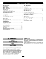
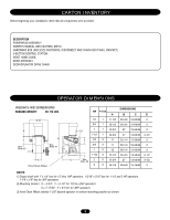
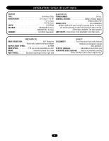
TABLE OF CONTENTS SPECIFICATIONS Carton Inventory 3 Operator Dimensions 3 Operator Specifications 4 PREPARATION Hand Chain Right/Left Conversion 5 Disconnect Lever Right/Left Conversion 5 Horizontal Mounting Conversion 5 INSTALLATION Mount the Operator 6 Manual Operation 7 Entrapment Protection Accessories 8 ADJUSTMENT Adjust Torque Limiter Clutch 9 Brake Adjustment 9 POWER WIRING Power Wiring Connections 10 CONTROL WIRING Determine Wiring Type 11 Special Control Wiring 11 Mounting Instructions 11 Radio Controls 12 Additional Access Control Equipment 12 External Interlock Switch 12 TEST THE SYSTEM 12 DIAGRAMS 1 Phase Schematic Diagram 13 1 Phase Wiring Diagram 14 3 Phase Schematic Diagram 15 3 Phase Wiring Diagram 16 OPTIONAL PROGRAMMING Connect Reversing Edge Device (Optional 17 MAINTENANCE SCHEDULE 18 REPAIR PARTS Repair Parts Kits - Electrical Box 20 Electrical Box 21 Repair Parts Kits - Model GH 22 Model GH 23 Control Connection Diagram 24 WARNING Mechanical CAWWUAATRRIONNNIINNGG Electrical CAWUATRIONNING When you see these Safety Symbols and Signal Words on the following pages, they will alert you to the possibility of serious injury or death if you do not comply with the warnings that accompany them. The hazard may come from something mechanical or from electric shock. Read the warnings carefully. When you see this Signal Word on the following pages, it will alert you to the possibility of damage to your door and/or the AVERTISSEMENT door operator if you do not comply with the cautionary statements that accompany it. Read them carefully. IMPORTANT NOTES: WARNING • BEFORE attempting to install, operate or maintain the operator, you must read and fully understand this manual and follow all safety instructions. WWAARRNNIINNGG • DO NOT attempt repair or service of your commercial door and gate operator unless you are an Authorized Service Technician. WARNING AVERTISSEMENT AAAVVTEETRRETTNIISSTISSOEENMMEENNTT 2 AAVVEERRTTIISSSSEEMMEENNTT

  • 1
  • 2
  • 3
  • 4
  • 5
  • 6
  • 7
  • 8
  • 9
  • 10
  • 11
  • 12
  • 13
  • 14
  • 15
  • 16
  • 17
  • 18
  • 19
  • 20
  • 21
  • 22
  • 23
  • 24

When you see these Safety Symbols and Signal Words on the
following pages, they will alert you to the possibility of
serious
injury
or
death
if you do not comply with the warnings that
accompany them. The hazard may come from something
mechanical or from electric shock. Read the warnings carefully.
When you see this Signal Word on the following pages, it will
alert you to the possibility of damage to your door and/or the
door operator if you do not comply with the cautionary
statements that accompany it. Read them carefully.
Mechanical
Electrical
TABLE OF CONTENTS
WARNING
WARNING
WARNING
WARNING
CAUTION
CAUTION
2
SPECIFICATIONS
Carton Inventory . . . . . . . . . . . . . . . . . . . . . . . . . . . . . . . . . . . . . 3
Operator Dimensions
. . . . . . . . . . . . . . . . . . . . . . . . . . . . . . . . . 3
Operator Specifications. . . . . . . . . . . . . . . . . . . . . . . . . . . . . . . . 4
PREPARATION
Hand Chain Right/Left Conversion . . . . . . . . . . . . . . . . . . . . . . . 5
Disconnect Lever Right/Left Conversion. . . . . . . . . . . . . . . . . . . 5
Horizontal Mounting Conversion
. . . . . . . . . . . . . . . . . . . . . . . . 5
INSTALLATION
Mount the Operator
. . . . . . . . . . . . . . . . . . . . . . . . . . . . . . . . . . 6
Manual Operation . . . . . . . . . . . . . . . . . . . . . . . . . . . . . . . . . . . . 7
Entrapment Protection Accessories
. . . . . . . . . . . . . . . . . . . . . . 8
ADJUSTMENT
Adjust Torque Limiter Clutch
. . . . . . . . . . . . . . . . . . . . . . . . . . . 9
Brake Adjustment . . . . . . . . . . . . . . . . . . . . . . . . . . . . . . . . . . . . 9
POWER WIRING
Power Wiring Connections . . . . . . . . . . . . . . . . . . . . . . . . . . . . 10
CONTROL WIRING
Determine Wiring Type . . . . . . . . . . . . . . . . . . . . . . . . . . . . . . . 11
Special Control Wiring
. . . . . . . . . . . . . . . . . . . . . . . . . . . . . . . 11
Mounting Instructions
. . . . . . . . . . . . . . . . . . . . . . . . . . . . . . . 11
Radio Controls
. . . . . . . . . . . . . . . . . . . . . . . . . . . . . . . . . . . . . 12
Additional Access Control Equipment. . . . . . . . . . . . . . . . . . . . 12
External Interlock Switch
. . . . . . . . . . . . . . . . . . . . . . . . . . . . . 12
TEST THE SYSTEM
. . . . . . . . . . . . . . . . . . . . . . . . . . . . . . . .
12
DIAGRAMS
1 Phase Schematic Diagram. . . . . . . . . . . . . . . . . . . . . . . . . . . 13
1 Phase Wiring Diagram. . . . . . . . . . . . . . . . . . . . . . . . . . . . . . 14
3 Phase Schematic Diagram. . . . . . . . . . . . . . . . . . . . . . . . . . . 15
3 Phase Wiring Diagram. . . . . . . . . . . . . . . . . . . . . . . . . . . . . . 16
OPTIONAL PROGRAMMING
Connect Reversing Edge Device (Optional). . . . . . . . . . . . . . . . .17
MAINTENANCE SCHEDULE
. . . . . . . . . . . . . . . . . . . . . . . . .18
REPAIR PARTS
Repair Parts Kits - Electrical Box
. . . . . . . . . . . . . . . . . . . . . . . .20
Electrical Box
. . . . . . . . . . . . . . . . . . . . . . . . . . . . . . . . . . . . . . .21
Repair Parts Kits - Model GH . . . . . . . . . . . . . . . . . . . . . . . . . . .22
Model GH . . . . . . . . . . . . . . . . . . . . . . . . . . . . . . . . . . . . . . . . . .23
Control Connection Diagram. . . . . . . . . . . . . . . . . . . . . . . . . . . .24
IMPORTANT NOTES:
BEFORE attempting to install, operate or maintain the operator,
you must read and fully understand this manual and follow all
safety instructions.
DO NOT attempt repair or service of your commercial door and
gate operator unless you are an Authorized Service Technician.