LiftMaster HCTDCU HCTDCU Quick Start Guide Manual - Page 1
LiftMaster HCTDCU Manual
 |
View all LiftMaster HCTDCU manuals
Add to My Manuals
Save this manual to your list of manuals |
Page 1 highlights
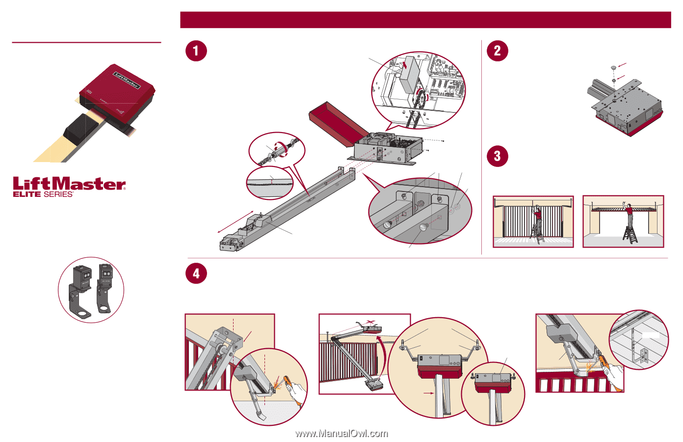
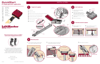
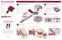
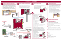
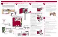
Model HCTDCU QuickStart for single gate/door application HCTDCU Motor Unit HCT08 8 Foot Rail HCT10 10 Foot Rail HCT12 12 Foot Rail 2016 UL 325 Gate Operators require use of LiftMaster external monitored entrapment protection devices. This QuickStart is intended to highlight a single gate/door application. Each application is unique and it is the responsibility of the purchaser, installer and end user to ensure that the total gate/door system is installed and operated properly. Refer to the installation manual for complete information regarding installation, testing, and programming. 01-38474 845 Larch Avenue Elmhurst, Illinois 60126-1196 LiftMaster.com © 2016, LiftMaster - All Rights Reserved INSTALLATION Connect rail to operator. 1 Open the cover. 2 Remove the chain guard. 3 Align the key holes on the end of the rail with the cap screws on the chassis. 4 Attach the rail to the chassis with the hardware provided. 5 Move trolley to within 3 feet (.9 m) of the end of the rail. 6 Wrap the chain around the output sprocket. 7 Adjust the chain tension. 8 Replace chain guard. Turnbuckle 7 Hex Nut Top of Rail Chain Guard 3 1/4" (.64 cm) Max. Within 3 feet (.9 m) 5 Trolley 2 6 1 Cap Screw Washer Nut 4 Carriage Bolt Mount the operator. 1 Center the header bracket in the opening and bolt or weld the header bracket to the wall. 2 Lift the operator and align with center mark on ceiling. Bolt the operator to the ceiling. Install vented plug. 1 Remove the dome plug from the operator chassis. 2 Remove the solid plug in the gear reducer and replace it with the vented plug (provided in bag with manual). 3 Tighten the vented plug with a socket or Allen wrench. 4 Re-insert the dome plug. Dome Plug Vented Plug Determine location for operator. 1 With the gate/door closed, mark the center. 2 Open the gate/door and mark the center point on the ceiling. 3 Bolt or weld arm to gate/door. Header Bracket Header Bracket Concrete Anchor 1/2" x 3 1/2" Brackets (not provided) Flush Mount Arm Temporary Support Post OR Door Arm DOOR INSTALLATION
-
 1
1 -
 2
2 -
 3
3 -
 4
4 -
 5
5 -
 6
6
 |
 |