LiftMaster J J -New style with thermal overload Manual
LiftMaster J Manual
 |
View all LiftMaster J manuals
Add to My Manuals
Save this manual to your list of manuals |
LiftMaster J manual content summary:
- LiftMaster J | J -New style with thermal overload Manual - Page 1
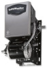
FACTORYSET C2 Wiring See page 8 for other wiring configurations OWNER'S MANUAL J H HJ INDUSTRIAL DUTY COMMERCIAL DOOR OPERATOR 2 YEAR WARRANTY Serial # Box Installation Date NOT FOR RESIDENTIAL USE - LiftMaster J | J -New style with thermal overload Manual - Page 2
11 Special Control Wiring 11 ATTENTION Mounting Instructions 11 something mechanical or from electric shock. Read the manual and follow all safety instructions. AAVTETRETNITSISOENMENT • DO NOT attempt repair or service of your commercial door and gate operator unless you are an Authorized Service - LiftMaster J | J -New style with thermal overload Manual - Page 3
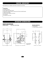
Hoist Wall Bracket) 3-Button Control Station Hoist Hand Chain (Models H & HJ Only) Door Sprocket Door/Operator Drive Chain OPERATOR DIMENSIONS WEIGHTS AND DIMENSIONS HANGING WEIGHT: 80-110 LBS. (36.3-49.9 kg) 14.44" 7.27" 7.17" 14.60" 4.63" MOUNTING DIMENSIONS A - Wall Mounting B - Bracket - LiftMaster J | J -New style with thermal overload Manual - Page 4
, open override plus wiring for sensing device to reverse. (Other types available. See chart, Pg. 11) LIMIT ADJUST: . . . . .Linear driven, fully adjustable screw type cams. Adjustable to 30 feet. MECHANICAL DRIVE REDUCTION Primary: Heavy duty (5L) V-Belt Secondary: #48 chain/sprocket; Output: #50 - LiftMaster J | J -New style with thermal overload Manual - Page 5
order. The handing is indicated by last letter of the model name (R or L). The hand chain wheel can not be switched on site. If your installation causes the hand chain to hang in the door opening, hook the chain off to the side near the top of the door jamb. Shaft Support Bracket with Bearing (Not - LiftMaster J | J -New style with thermal overload Manual - Page 6
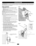
are aligned. When in position, secure the operator to wall or mounting bracket. 7. Align sprockets and secure (Figure 3). 8. Install Hand Chain (Models H and HJ only) Place hand chain around hand chain wheel. Be sure to pass it through both openings in the chain guide. Remove enough links so chain - LiftMaster J | J -New style with thermal overload Manual - Page 7
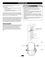
Electrical Interlock with Hoist for Models H and HJ MODEL J This operator has a floor level disconnect chain to disconnect the door from the door operator. 1. To disengage, pull the chain and secure in the disengaged position by slipping the end through the keyhole bracket mounted on the wall - LiftMaster J | J -New style with thermal overload Manual - Page 8
for door industry type operators with an isolated normally open (N.O.) output are compatible with your operator. This includes pneumatic and electric edges, and through CAUTION reversing sensors when the 3-button control station is out of sight of door or ANY other control (automatic or manual) is - LiftMaster J | J -New style with thermal overload Manual - Page 9
be possible to stop the door by hand during travel. 4. Reinstall cotterpin. WARNING To prevent possible SERIOUS INJURY or DEATH, install CAUTION reversing sensors when the 3-button control station is out of sight of the door or ANY other control (automatic or manual) is used. Reversing devices are - LiftMaster J | J -New style with thermal overload Manual - Page 10
secured, at that time the unit may be returned to service. • Disconnect power at the fuse box BEFORE proceeding. Operator MUST be properly grounded and connected in accordance with local electrical codes. The operator should be on a separate fused line . • ALL power and control wiring MUST be run in - LiftMaster J | J -New style with thermal overload Manual - Page 11
On all models with type B2 control wiring, a terminal bracket marked R1 R2 R3 is located on the outside of the electrical enclosure. All standard radio control receivers (single channel residential type) may be mounted to this bracket. The operator will then open a fully closed door, close a fully - LiftMaster J | J -New style with thermal overload Manual - Page 12
1 2 WHITE OPEN SEE NOTE 2 OPEN CLOSE STOP EXT. INTLK. TO OPEN AND CLOSE SAFETY EDGE L1 L2 1 PHASE POWER IN (SEE NOTE 3) * - Shipped from Factory CLOSE CONTROL OPERATION. 3) TRANSFORMER PRIMARY & RELAY VOLTAGE SAME AS LINE VOLTAGE. 4) SINGLE PHASE UNITS ARE EQUIPPED WITH AN EXTERNAL LINE - LiftMaster J | J -New style with thermal overload Manual - Page 13
FOR 230V 1PH OPERATION. 3) TRANSFORMER PRIMARY & RELAY VOLTAGE SAME AS LINE VOLTAGE. 4) SINGLE PHASE UNITS ARE EQUIPPED WITH AN EXTERNAL LINE BREAK DEVICE, AND MAY BE EQUIPPED WITH AN ADDITIONAL INTERNAL PILOT DUTY THERMAL O/L DEVICE. * - Shipped from Factory CLOSE CONTROL WIRING OPTIONS *C2 - LiftMaster J | J -New style with thermal overload Manual - Page 14
OPEN CLOSE STOP 4 5 7 10 L1 L2 L3 GROUND EXT. INTLK. TO OPEN AND CLOSE SAFETY EDGE L1 L2 L3 3 PHASE POWER IN (SEE NOTE 2) * - Shipped from Factory CLOSE CONTROL AS LINE VOLTAGE. 3) THREE PHASE UNITS MAY BE EQUIPPED WITH AN INTERNAL PILOT DUTY THERMAL OVERLOAD DEVICE, OR AN EXTERNAL LINE - LiftMaster J | J -New style with thermal overload Manual - Page 15
(BK) TO MOTOR HAND CHAIN INTL'K SWITCH (WHEN PRESENT) 5 (BRN) NC C (YEL) (BRN) PRI. T1 (SEE NOTE 2) 24VAC SEC. (YEL) 14 OP 1 (OR) 13 (OR) OPEN (OR) LIMIT SWITCH PILOT DUTY THERMAL OVERLOAD DEVICE, OR AN EXTERNAL LINE MONITORING DEVICE. * - Shipped from Factory CLOSE CONTROL WIRING - LiftMaster J | J -New style with thermal overload Manual - Page 16
the Safety Instructions, know how to electrically operate the door in a safe manner, and know how to use the manual disconnect operation of the door operating system. WARNING Do not place hands or tools in or near the operator when the CAUTION power is on or when testing control or safety - LiftMaster J | J -New style with thermal overload Manual - Page 17
OPERATOR NOTES 17 - LiftMaster J | J -New style with thermal overload Manual - Page 18
ELECTRICAL BOX - ILLUSTRATED PARTS S2 S1 S6 S5 S3 S7 S8 S4 L3 S9 L1 10 9 L7 L5 L8 3 L6 L2 1 2 11 18 4 8 L2 L6 L4 7 6 - LiftMaster J | J -New style with thermal overload Manual - Page 19
pilot duty thermal O/L device, or an external line break device. COMPLETE ELECTRICAL BOX REPLACEMENT KITS COMPLETE FRAME REPLACEMENT KITS K73-JFRAME Frame Model J K73-HFRAME-R Frame Model H (Right Hand) K73-HFRAME-L Frame Model H (Left Hand) K73-HJFRAME-R Frame Model H (Right Hand) K73 - LiftMaster J | J -New style with thermal overload Manual - Page 20
3 10-13899 Electrical Box Cover 1 4 21-5xxx (See Variable Components) 1 6 24-xxx-x (See Variable Components) 1 7 24-24-1 24Vac DPDT Relay 1 8 25-2xxx (See Variable Components) 1 9 25-4xxx (See Variable Components) 1 10 42-10040 Terminal Block, Radio 1 11 42-110 Terminal - LiftMaster J | J -New style with thermal overload Manual - Page 21
OPERATOR NOTES 21 - LiftMaster J | J -New style with thermal overload Manual - Page 22
ILLUSTRATED PARTS - MODEL J 10 11 12 2 3 C9 9 C10 C8 C19 C6 C11 8 5 C5 C12 C17 C15 C2 C18 C14 1 C16 C13 C5 C4 C7 C17 C3 C1 O4 011 O8 O12 O9 C2 C17 C5 O12 O11 O5 O8 O9 O2 O1 O3 O10 O6 O7 O12 6 7 1 22 - LiftMaster J | J -New style with thermal overload Manual - Page 23
Walled Receiver 4 Spacer 3 K72-19975 CLUTCH SHAFT ASSEMBLY KIT ITEM C1 C2 C3 C4 C5 C6 C7 C8 C9 C10 C11 C12 C13 C14 PART # 11-19470 12-19504 15-19480 15-19484 158A0056 18-19487 75-19985 80-19473 80-19474 80-19475 80-19476 80-19846 80-206-11 86-RP10-112 - LiftMaster J | J -New style with thermal overload Manual - Page 24
ILLUSTRATED PARTS - MODEL H 9 10 11 2 3 C7 8 1 C13 C12 C11 C14 C10 C8 C9 C4 C6 C5 C13 C1 C3 C5 C13 C2 O4 011 O8 O12 O9 C2 C13 C5 O12 O11 O5 O8 O9 O1 O3 O6 O7 O12 O2 O10 6 7 1 24 - LiftMaster J | J -New style with thermal overload Manual - Page 25
" - 18 3 Roll Pin, 5/16" x 1.75" 1 Thin Walled Receiver 4 Spacer 3 K72-19975 CLUTCH SHAFT ASSEMBLY KIT ITEM C1 C2 C3 C4 C5 C6 C7 C8 C9 C10 C11 C12 C13 C14 PART # 11-19471 12-19504 15-19480 15-19481 158A0056 18-11379 75-10884 75-19985 75-19986 80-10022 80-206-11 80-19418 80-RP10 - LiftMaster J | J -New style with thermal overload Manual - Page 26
10 11 12 2 3 C9 ILLUSTRATED PARTS - MODEL HJ 26 9 C10 C8 C19 C6 C11 8 5 C5 C12 C17 C15 C2 C18 C14 1 C16 C13 C5 C4 C7 C17 C3 C1 O4 011 O8 O12 O9 C2 C17 C5 O12 O11 O5 O8 O9 O2 O1 O3 O10 O6 O7 O12 6 7 1 - LiftMaster J | J -New style with thermal overload Manual - Page 27
-19473 12-19504 15-19480 15-19484 158A0056 18-11379 18-19487 75-10884 75-19985 75-19986 80-10022 80-19473 80-19474 80-19475 80-19476 80-19846 80-206-11 86-RP10-112 80-RP10-208 DESCRIPTION QTY Shaft, HJ Clutch 1 1" Keyed Flange Bearing 2 Dual Sprocket 32/14 1 Splined Core Sprocket 1 E-Ring - LiftMaster J | J -New style with thermal overload Manual - Page 28
R2 R3 EXTERNAL TERMINAL BLOCK Sensing Device RADIO CONTROL ALL CONTROL WIRING TYPES TIMER TO CLOSE w/ WARNING LIGHT ALL CONTROL WIRING TYPES * T1 WIRING - RADIO TO OPEN ONLY EXTERNAL INTERLOCK Warning Light will activate 15 sec. before door closes. 11 12 13 14 Auxiliary Terminal Block Remove
-
 1
1 -
 2
2 -
 3
3 -
 4
4 -
 5
5 -
 6
6 -
 7
7 -
8
-
9
-
10
-
11
-
12
-
13
-
14
-
15
-
16
-
17
-
18
-
19
-
20
-
21
-
22
-
23
-
24
-
25
-
26
-
27
-
28
 |
 |

O W N E R ’ S M A N U A L
J H HJ
INDUSTRIAL DUTY COMMERCIAL DOOR OPERATOR
NOT FOR RESIDENTIAL USE
Serial # Box
Installation Date
2
YEAR
WARRANTY
C2 Wiring
F A C T O R Y S E T
See page 8 for
other wiring
configurations