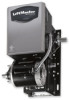
LiftMaster J J -New style with thermal overload Manual - Page 2

Table Of Contents

Page 2 highlights

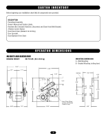
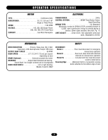
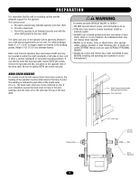
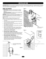
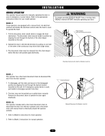
TABLE OF CONTENTS SPECIFICATIONS Carton Inventory 3 Operator Dimensions 3 Operator Specifications 4 PREPARWATAIORN NING Hand Chain Handing 5 INSTACLLAATUIOTN ION Mount the Operator 6 Manual Operation 7 Entrapment Protection Accessories 8 ADJUSTMENT Limit Switch Adjustment 8 Brake Adjustment 9 Clutch Adjustment and Auxiliary Reversal System 9 POWER WIRING CONNECTIONS Safety Warnings 10 Power Wiring Connections 10 Ground Wiring Connections 10 CAONVTREORL WTIIRSINSG EMENT Determine Wiring Type 11 Special Control Wiring 11 ATTENTION Mounting Instructions 11 DIAGRAMS Single Phase Wiring Diagram - 10118-1 12 Single Phase Schematic Diagram - 10118-1 13 Three Phase Wiring Diagram - 10118-1 14 Three Phase Schematic Diagram - 10118-1 15 TEST THE SYSTEM 16 MAINTENANCE SCHEDULE 16 Operator Notes 17 REPLACEMENT PARTS Electrical Box 18 Replacement Parts Kits 19 - 20 Operator Notes 21 Repair Parts Kits - Model J 22 - 23 ADVERTENCIA Repair Parts Kits - Model H 24 - 25 Repair Parts Kits - Model HJ 26 - 27 Control Connection Diagram 28 PRECAUCIÓN WARNING Mechanical CWWAAUARTRINNOIINNNGG Electrical CAWUATRIONNING When you see these Safety Symbols and Signal Words on the following pages, they will alert you to the possibility of serious injury or death if you do not comply with the warnings that accompany them. The hazard may come from something mechanical or from electric shock. Read the warnings carefully. When you see this Signal Word on the following pages, it will alert you to the possibility of damage to your door and/or the door operator if you do not comply with the cautionary AVERTISSEMENT statements that accompany it. Read them carefully. IMPORTANT NOTES: • BEFORE attempAtAingAVVtoTEEinTRsRtaElTlT, NoIIpSSeTraSStIeOEEor NMmMaiEnEtaNiNn tThTe operator, you must read and fully understand this manual and follow all safety instructions. AAVTETRETNITSISOENMENT • DO NOT attempt repair or service of your commercial door and gate operator unless you are an Authorized Service Technician. ADVERTENCIA PAARDDEVVCEEARRUTTCEEIÓNNCCNIIAA PRAEDCVAEURCTIEÓNNCIA 2

  • 1
  • 2
  • 3
  • 4
  • 5
  • 6
  • 7
  • 8
  • 9
  • 10
  • 11
  • 12
  • 13
  • 14
  • 15
  • 16
  • 17
  • 18
  • 19
  • 20
  • 21
  • 22
  • 23
  • 24
  • 25
  • 26
  • 27
  • 28

When you see these Safety Symbols and Signal Words on the
following pages, they will alert you to the possibility of
serious
injury
or
death
if you do not comply with the warnings that
accompany them. The hazard may come from something
mechanical or from electric shock. Read the warnings carefully.
When you see this Signal Word on the following pages, it will
alert you to the possibility of damage to your door and/or the
door operator if you do not comply with the cautionary
statements that accompany it. Read them carefully.
Mechanical
Electrical
TABLE OF CONTENTS
WARNING
WARNING
WARNING
WARNING
CAUTION
CAUTION
2
SPECIFICATIONS
Carton Inventory . . . . . . . . . . . . . . . . . . . . . . . . . . . . . . . . . . . . . 3
Operator Dimensions
. . . . . . . . . . . . . . . . . . . . . . . . . . . . . . . . . 3
Operator Specifications. . . . . . . . . . . . . . . . . . . . . . . . . . . . . . . . 4
PREPARATION
Hand Chain Handing . . . . . . . . . . . . . . . . . . . . . . . . . . . . . . . . . . 5
INSTALLATION
Mount the Operator. . . . . . . . . . . . . . . . . . . . . . . . . . . . . . . . . . . 6
Manual Operation . . . . . . . . . . . . . . . . . . . . . . . . . . . . . . . . . . . . 7
Entrapment Protection Accessories
. . . . . . . . . . . . . . . . . . . . . . 8
ADJUSTMENT
Limit Switch Adjustment. . . . . . . . . . . . . . . . . . . . . . . . . . . . . . . 8
Brake Adjustment . . . . . . . . . . . . . . . . . . . . . . . . . . . . . . . . . . . . 9
Clutch Adjustment and Auxiliary Reversal System . . . . . . . . . . . 9
POWER WIRING CONNECTIONS
Safety Warnings . . . . . . . . . . . . . . . . . . . . . . . . . . . . . . . . . . . . 10
Power Wiring Connections . . . . . . . . . . . . . . . . . . . . . . . . . . . . 10
Ground Wiring Connections . . . . . . . . . . . . . . . . . . . . . . . . . . . 10
CONTROL WIRING
Determine Wiring Type . . . . . . . . . . . . . . . . . . . . . . . . . . . . . . . 11
Special Control Wiring
. . . . . . . . . . . . . . . . . . . . . . . . . . . . . . . 11
Mounting Instructions. . . . . . . . . . . . . . . . . . . . . . . . . . . . . . . . 11
DIAGRAMS
Single Phase Wiring Diagram – 10118-1 . . . . . . . . . . . . . . . . . 12
Single Phase Schematic Diagram – 10118-1 . . . . . . . . . . . . . . 13
Three Phase Wiring Diagram – 10118-1. . . . . . . . . . . . . . . . . . 14
Three Phase Schematic Diagram – 10118-1. . . . . . . . . . . . . . . 15
TEST THE SYSTEM
. . . . . . . . . . . . . . . . . . . . . . . . . . . . . . . 16
MAINTENANCE SCHEDULE
. . . . . . . . . . . . . . . . . . . . . . . 16
Operator Notes . . . . . . . . . . . . . . . . . . . . . . . . . . . . . . . . . . . . . 17
REPLACEMENT PARTS
Electrical Box
. . . . . . . . . . . . . . . . . . . . . . . . . . . . . . . . . . . . . . 18
Replacement Parts Kits. . . . . . . . . . . . . . . . . . . . . . . . . . . 19 – 20
Operator Notes . . . . . . . . . . . . . . . . . . . . . . . . . . . . . . . . . . . . . 21
Repair Parts Kits - Model J. . . . . . . . . . . . . . . . . . . . . . . . 22 – 23
Repair Parts Kits - Model H
. . . . . . . . . . . . . . . . . . . . . . . 24 – 25
Repair Parts Kits - Model HJ
. . . . . . . . . . . . . . . . . . . . . . 26 – 27
Control Connection Diagram. . . . . . . . . . . . . . . . . . . . . . . . . . . 28
IMPORTANT NOTES:
• BEFORE attempting to install, operate or maintain the operator,
you must read and fully understand this manual and follow all
safety instructions.
• DO NOT attempt repair or service of your commercial door and
gate operator unless you are an Authorized Service Technician.