LiftMaster LA500UL Installation Manual - Page 10
Step 1 Position the Brackets, DIMENSION CHART
 |
View all LiftMaster LA500UL manuals
Add to My Manuals
Save this manual to your list of manuals |
Page 10 highlights
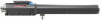
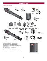
INSTALLATION Step 1 Position the Brackets If this operator is a replacement for a Miracle-One™ operator, use the existing post bracket and gate bracket. Remove the Miracle-One™ operator from the brackets and proceed to the next step. NOTE: The ideal installation measurements are A = 7-3/4" (19.7 cm) and B = 81/2" (21.6 cm). If different measurements are used, the sum of A and B cannot be greater than 18" (45.7 cm). DIMENSION CHART If your application is Push-to-Open, refer to the illustrations in the Appendix. The measurements shown below are typical for a standard installation. Your installation may be different. The gate bracket MUST be installed in an area that can withstand heavy forces. Additional reinforcement steel plates may be necessary for mounting. 1. Close the gate. 2. Choose a vertical mounting location for the post bracket. A 7-3/4" (19.7 cm) 8-1/2" (21.6 cm) 9" (22.9 cm) 9" (22.9 cm) 7-1/2" (19.1 cm) B 8-1/2" (21.6 cm) 7-3/4" (19.7 cm) 9" (22.9 cm) 8-1/2" (21.6 cm) 7-1/2" (19.1 cm) 3. Place a measuring tape under the center of the gate hinge point and measure out dimension A (see chart). 4. Use a screwdriver or dowel rod to temporarily mark the location of the first measurement (Figure 1). 5. Measure out dimension B (see chart) from the previous mark. Use a screwdriver to mark the location of the second measurement (Figure 1). 6. Align the post bracket as close as possible above the screwdriver or dowel rod and tack weld the post bracket in the desired vertical position. 7. Position a level on the post bracket and measure 35-1/2" (90.2 cm) over from the center hole of the post bracket and mark the location on the gate (Figure 2). 8. Measure 2-1/4" (6.4 cm) down from the previous mark and center the bracket on this mark (Figure 3). Tack weld the gate bracket in this position. NOTES: l There should only be a maximum of 4" (10.2 cm) from the center of the hinge to the edge of the post or column (Figure 1). If the distance is greater than 4" (10.2 cm) entrapment protection for this area is required. l While the gate is in the fully open position, the operator needs a clearance of 11-1/4" (28.6 cm) as shown (Figure 2). 10
-
 1
1 -
2
-
3
-
4
-
 5
5 -
 6
6 -
 7
7 -
 8
8 -
 9
9 -
 10
10 -
 11
11 -
 12
12 -
 13
13 -
 14
14 -
 15
15 -
16
-
17
-
18
-
19
-
20
-
21
-
22
-
23
-
24
-
25
-
26
-
27
-
28
-
29
-
30
-
31
-
32
-
33
-
34
-
35
-
36
-
37
-
38
-
39
-
40
-
41
-
42
-
43
-
44
-
45
-
46
-
47
-
48
-
49
-
50
-
51
-
52
-
53
-
54
-
55
-
56
 |
 |
