LiftMaster LA500UL Installation Manual - Page 43
Quick Close not, AUX Relay
 |
View all LiftMaster LA500UL manuals
Add to My Manuals
Save this manual to your list of manuals |
Page 43 highlights
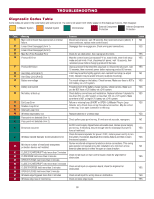
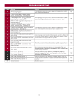
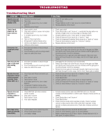
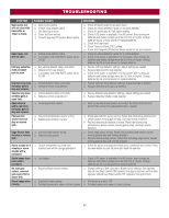
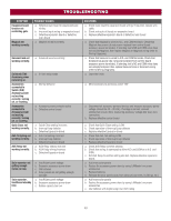
TROUBLESHOOTING SYMPTOM Expansion board function not controlling gate. Maglock not working correctly. POSSIBLE CAUSES a. Defective main board to expansionboard wiring b. Incorrect input wiring to expansion board c. Defective expansion board or defective main board a. Maglock wired incorrectly Solenoid lock not working correctly. a. Solenoid wired incorrectly Switched (SW) Accessory power remaining on. Accessories connected to Switch (SW) Accessory power not working correctly, turning off, or resetting. Accessories connected to Accessory power not working correctly, turning off, or resetting. Quick Close not working correctly. Anti-Tailgating not working correctly. AUX Relay not working correctly. a. In limit setup mode a. Normal behavior a. Accessory power protector active b. Defective control board a. Quick Close setting incorrect b. Interrupt loop detector c. Defective Expansion board a. Anti-Tail setting incorrect b. Interrupt loop detector c. Defective Expansion board a. AUX Relay setting incorrect b. AUX Relay wiring incorrect c. Defective Expansion board Solar operator not getting enough cycles per day. Solar operator, insufficient standby time. a. Insufficient panel wattage b. Excessive accessory power draw c. Old batteries d. Solar panels are not getting enough sunlight a. Insufficient panel wattage b. Excessive accessory power draw c. Battery capacity too low SOLUTIONS a. Check main board to expansion board wiring. If required, replace wire cable. b. Check wiring to all inputs on expansion board. c. Replace defective expansion board or defective main board a. Check that Maglock is wired to N.C. and COM terminals. Check that Maglock has power (do not power maglock from control board accessory power terminals). If shorting lock's NO and COM wires does not activate Maglock, then replace Maglock or Maglock wiring (refer to Wiring Diagrams). a. Check that Solenoid is wired to N.O. and COM terminals. Check that Solenoid has power (do not power solenoid from control board accessory power terminals). If shorting lock's NC and COM wires does not activate Solenoid, then replace Solenoid lock or Solenoid wiring (refer to Wiring Diagrams). a. Learn the limits a. Move accessory to accessory power "ON" a. Disconnect all accessory powered devices and measure accessory power voltage (should be 23 - 30 Vdc). If voltage is correct, connect accessories one at a time, measuring accessory voltage after every new connection. b. Replace defective control board a. Check that Quick Close setting is ON b. Check operation of Interrupt Loop detector c. Replace defective Expansion board a. Check that Anti-Tail setting is ON b. Check operation of Interrupt Loop detector c. Replace defective Expansion board a. Check AUX Relay switches settings b. Check that wiring is connected to either N.O. and COM or to N.C. and COM. c. Set AUX Relay to another setting and test. Replace defective expansion board. a. Add more solar panels b. Reduce the accessory power draw by using LiftMaster low power accessories c. Replace batteries d. Relocate the solar panels away from obstructions (trees, buildings, etc.) a. Add more solar panels b. Reduce the accessory power draw by using LiftMaster low power accessories c. Use batteries with higher amp hour (AH) rating 43
-
 1
1 -
2
-
3
-
4
-
5
-
6
-
7
-
8
-
9
-
10
-
11
-
12
-
13
-
14
-
15
-
16
-
17
-
18
-
19
-
20
-
21
-
22
-
23
-
24
-
25
-
26
-
27
-
28
-
29
-
30
-
31
-
32
-
33
-
34
-
35
-
36
-
37
-
 38
38 -
 39
39 -
 40
40 -
 41
41 -
 42
42 -
 43
43 -
 44
44 -
 45
45 -
 46
46 -
 47
47 -
 48
48 -
49
-
50
-
51
-
52
-
53
-
54
-
55
-
56
 |
 |
