LiftMaster LM21AFCB LM21AFCB Manual - Page 2

Warning, Caution - parts

Page 2 highlights

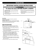
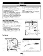
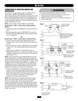
TABLE OF CONTENTS INTRODUCTION General Description 2 Agency Requirements 3 Specifications 3 Preparation 3 WARNING INSTALLATION Important Installation Warnings 4 CAUTION Mount the Release Device 4 WIRING Power Wiring Connections 5 Connections from Device to the Operator 6 Connections of Initiating Devices and Accessories 7 Optional Connections 8 ADJUSTMENTS DIP Switch Configuration Setting 9 Selectable Delay Settings (Switches 3 & 4 9 TESTING Test Release Device and Door Operator 10-11 AVERTISSEMENT Test Release Device With Battery Backup Without AC Power . .12 TROUBLESHOOTING Diagnostic LEDs 13 ATTENTION MAINTENANCE Maintenance 14 Enclosure Mounted LEDs Status Indicators 14 ACCESSORIES AND REPAIR PARTS 15 APPENDIX 16 WARNING Mechanical CAUTION WARNING WElAecRtricNalING CAWUATRIONNING When you see these Safety Symbols and Signal Words on the following pages, they will alert you to the possibility of serious injury or death if you do not comply with the warnings that accompany them. The hazard may come from something mechanical or from electric shock. Read the warnings carefully. When you see this Signal Word on the following pages, it will AVERTISSEMENT alert you to the possibility of damage to your door and/or the door operator if you do not comply with the cautionary statements that accompany it. Read them carefully. AAVTETRETNISTSIOENMENT IMPORTANT NOTAES:VERTISSEMENT • BEFORE attempting to install, operate or maintain the release AVERTISSEMENT device, you must read and fully understand this manual and follow all safety insAtruTctioTnsE. NTION • DO NOT attempt repair or service of your release device unless you are an Authorized Service Technician. INTRODUCTION GENERAL DESCRIPTION The LiftMaster® Fire Control LM21AFCB and LM21AFCBVB Release Device is UL/ULC listed normally energized fail-safe device incorporating state-of-the-art electronic control circuitry. This release device is designed to be used with manual doors or ADVERTENCIA motorized doors incorporating a reversing electric safety edge to create an automated door closing system. The high performance control panel responds to emergency conditions generated from an automatic initiating device. Upon PRECAUCIÓN activation, the device will then automatically close a motorized door or mechanically release a door in the absence of motorized operation. If the alarm is still present and power is available to the operator, a motorized door can be opened by depressing the open switch of the operator, after which the door will close again. If the door meets an obstruction while in alarm, the door will reverse and make three attempts to close, after which the motor will be shut off and the door will rest on the obstruction. The release device may also be optionally set to fully open the door and subsequently mechanically release the fire door onto the obstruction. ADVERTENCIA The device provides 3 count obstruction cycling. A safety timer within the device will turn the motor off and perform a mechanical release if the lower limit is not detected within a predetermined time period. Verify factory-installed options to PRECAUCIÓN desired features during initial testing. ADVERTENCIA Features include a selectable 10, 20, 30 or 60-second time delay ADVERTENCIA on alarm, remote test, motor voltage sensing, Form C relay output, lower limit detection, safety timer, battery support for ADVERTENCIA release device logic, smoke detectors, standard annunciators and PRECAUCIÓN trouble diagnostic capabilities (does not support operator). Operating voltage is 120Vac. As with all releasing device systems, maximum fire protection is provided when installed in accordance with factory specifications and used with fuse link systems. 2

  • 1
  • 2
  • 3
  • 4
  • 5
  • 6
  • 7
  • 8
  • 9
  • 10
  • 11
  • 12
  • 13
  • 14
  • 15
  • 16

When you see these Safety Symbols and Signal Words on the
following pages, they will alert you to the possibility of
serious
injury
or
death
if you do not comply with the warnings that
accompany them. The hazard may come from something
mechanical or from electric shock. Read the warnings carefully.
When you see this Signal Word on the following pages, it will
alert you to the possibility of damage to your door and/or the
door operator if you do not comply with the cautionary
statements that accompany it. Read them carefully.
Mechanical
Electrical
TABLE OF CONTENTS
WARNING
WARNING
WARNING
WARNING
CAUTION
CAUTION
2
INTRODUCTION
General Description . . . . . . . . . . . . . . . . . . . . . . . . . . . . . . . . . . .2
Agency Requirements
. . . . . . . . . . . . . . . . . . . . . . . . . . . . . . . . .3
Specifications . . . . . . . . . . . . . . . . . . . . . . . . . . . . . . . . . . . . . . . .3
Preparation . . . . . . . . . . . . . . . . . . . . . . . . . . . . . . . . . . . . . . . . . .3
INSTALLATION
Important Installation Warnings . . . . . . . . . . . . . . . . . . . . . . . . . .4
Mount the Release Device . . . . . . . . . . . . . . . . . . . . . . . . . . . . . .4
WIRING
Power Wiring Connections . . . . . . . . . . . . . . . . . . . . . . . . . . . . . .5
Connections from Device to the Operator
. . . . . . . . . . . . . . . . . .6
Connections of Initiating Devices and Accessories
. . . . . . . . . . .7
Optional Connections . . . . . . . . . . . . . . . . . . . . . . . . . . . . . . . . . .8
ADJUSTMENTS
DIP Switch Configuration Setting . . . . . . . . . . . . . . . . . . . . . . . . .9
Selectable Delay Settings (Switches 3 & 4) . . . . . . . . . . . . . . . . .9
TESTING
Test Release Device and Door Operator . . . . . . . . . . . . . . . .10-11
Test Release Device With Battery Backup Without AC Power
. .12
TROUBLESHOOTING
Diagnostic LEDs . . . . . . . . . . . . . . . . . . . . . . . . . . . . . . . . . . . . .13
MAINTENANCE
Maintenance . . . . . . . . . . . . . . . . . . . . . . . . . . . . . . . . . . . . . . . .14
Enclosure Mounted LEDs Status Indicators . . . . . . . . . . . . . . . .14
ACCESSORIES AND REPAIR PARTS
. . . . . . . . . . . . . . .15
APPENDIX
. . . . . . . . . . . . . . . . . . . . . . . . . . . . . . . . . . . . . . . .16
IMPORTANT NOTES:
• BEFORE attempting to install, operate or maintain the release
device, you must read and fully understand this manual and
follow all safety instructions.
• DO NOT attempt repair or service of your release device unless
you are an Authorized Service Technician.
GENERAL DESCRIPTION
The LiftMaster
®
Fire Control LM21AFCB and LM21AFCBVB
Release Device is UL/ULC listed normally energized fail-safe
device incorporating state-of-the-art electronic control circuitry.
This release device is designed to be used with manual doors or
motorized doors incorporating a reversing electric safety edge to
create an automated door closing system.
The high performance control panel responds to emergency
conditions generated from an automatic initiating device. Upon
activation, the device will then automatically close a motorized
door or mechanically release a door in the absence of motorized
operation. If the alarm is still present and power is available to
the operator, a motorized door can be opened by depressing the
open switch of the operator, after which the door will close again.
If the door meets an obstruction while in alarm, the door will
reverse and make three attempts to close, after which the motor
will be shut off and the door will rest on the obstruction. The
release device may also be optionally set to fully open the door
and subsequently mechanically release the fire door onto the
obstruction.
The device provides 3 count obstruction cycling. A safety timer
within the device will turn the motor off and perform a
mechanical release if the lower limit is not detected within a
predetermined time period. Verify factory-installed options to
desired features during initial testing.
Features include a selectable 10, 20, 30 or 60-second time delay
on alarm, remote test, motor voltage sensing, Form C relay
output, lower limit detection, safety timer, battery support for
release device logic, smoke detectors, standard annunciators and
trouble diagnostic capabilities (does not support operator).
Operating voltage is 120Vac.
As with all releasing device systems, maximum fire protection is
provided when installed in accordance with factory specifications
and used with fuse link systems.
INTRODUCTION