LiftMaster LM21AFCB LM21AFCB Manual - Page 6
Caution - door openers
 |
View all LiftMaster LM21AFCB manuals
Add to My Manuals
Save this manual to your list of manuals |
Page 6 highlights
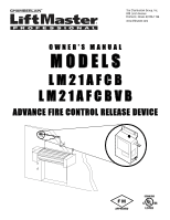
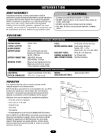
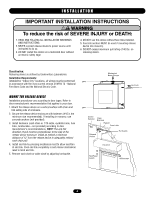
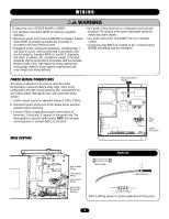
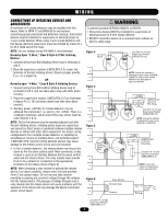
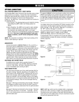
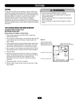
WIRING WARNING CONNECTIONS FROM DEVICE TO THE OPERATOR NOTE: For low voltage wiring #18 AWG is recommended. OPERATOR CONNECTIONS 1. Connect terminals 11 and 12 from the release device to the transformer secondary in the door operator. The required voltage should be 24-30Vac. NOTE: This connection must be made in order to avoid a mechanical release in alarm conditions when the door is not closed (Figure 2). 2. Connect release device to auxiliary limit switches on the operator. These are required and must be provided by the door operator manufacturer. Auxiliary Closed Limit Switch (Figure 1): Connect a wire from the common and N/O of the auxiliary limit switch to terminals 13 and 14 on the release device. This input will not allow a mechanical release if the auxiliary close limit is activated. This circuit also turns off annunciators when the auxiliary close limit is activated. CAUTION To prevent DAMAGE to the circuit board, auxiliary limit switches MUST be provided as dry contacts and may not be used in conjunction with the simultaneous switching of a motor control or ANY other voltage through the same contacts. Connections of this type will result in immediate damage to the release device. Auxiliary Open Limit Switch (Figure 1): Connect a wire from the common and N/O of the auxiliary limit switch to terminals 14 and 15 on the release device. A connection to an auxiliary up limit switch is required for 3-cycle obstruction count feature. Adjust the auxiliary open limit to activate just before the operators open limit is activated. AVERTISSEMENT 3. Connect wires from terminals 7, 8, 9, and 10 to the door operator terminals that are used for 3-button station (for use with N/O 'Close' switch, N/O 'Open' switch and N/C 'Stop' ATTENTION switch). The close relay output latches to initiate a door closure through the operator after the factory set delay. Figure 1 Auxiliary Limit Switches Auxiliary Close Limit (N.O.) Figure 2 Speaker - Voice Board Model Only + Speaker - Speaker (4) End of Line Relay (4) LMEOLRES-2-2 Safety Edge Operator Common Auxiliary Open Limit (N.O.) 3-Button (2) Auxiliary Limit (3) Wall Mounted Station Switches (5) Annunciator Test/Reset Switch 2.2 kOhm 2.2 kOhm .75A Maximum Current During Alarm Auxiliary Open Limit (N.O.) (4) Safety Edge Safety Edge Common Open Button Input Close Button Input Stop Button Input 3-Button Common Control Voltage Control Ground Open Button Close Button Stop Button Auxiliary Close Limit (N.O.) (4) Smoke Detector 2-Wire Smoke Detector Wiring (4 Detector Maximum) Smoke Detector OR Smoke Detector 24 Vdc 4-Wire Smoke Detector Wiring (4 Detector Maximum) Smoke Detector D C 2.2 kOhm Red Yellow D C (PU) (YE) ADVERTENCIA LMEOLRES-2-2 Voice Board (1) 2-Wire Smoke Detector Wiring 4-Wire Smoke Detector Wiring PRECAUCIÓN Additional Dry Contact BATTERY CONNECTION / MAINTENANCE Use two (2) 12V 4.5AH sealed lead acid batteries in series. Maximum charge current 1A. Replace batteries every 2 years. Black Wire to Black Terminal Battery Interconnect Wire Battery 1 Red to Battery 2 Black Red Wire to Red Terminal Battery 1 Battery 2 Power Con. TB2 POWER CONNECTION TB2 L1 L2 L3 Hot 120Vac 1-Phase Neutral 120Vac 1-Phase 6 Replace batteries every 2 years. Field Wiring shall consist of 22-18 AWG wiring. Use only 250 VAC, 2 Amp, 3 AG Slo-Blo fuses. 1. Supervised, power limited circuit, 20 Ohm maximum line impedance. 2. Unsupervised circuit, 20 Ohm maximum line impedance. 3. Unsupervised, power limited circuit, 20 Ohm maximum line impedance. 4. Maximum of 4 Class B Style A detectors. LMEOLRES-2-2 required for supervision. 5. Maximum of 2 Class B Style W notification appliances. 0.75 Amp at 24 VDC maximum. Supervised, non-power limited circuit. 20 Ohm maximum line impedance. Place 2.2 kOhm resistor between 16 & 20 if unused.
-
 1
1 -
 2
2 -
 3
3 -
 4
4 -
 5
5 -
 6
6 -
 7
7 -
 8
8 -
 9
9 -
 10
10 -
 11
11 -
 12
12 -
13
-
14
-
15
-
16
 |
 |