LiftMaster MGJ Installation Manual
LiftMaster MGJ Manual
 |
View all LiftMaster MGJ manuals
Add to My Manuals
Save this manual to your list of manuals |
LiftMaster MGJ manual content summary:
- LiftMaster MGJ | Installation Manual - Page 1
illustrated in this manual. 2 YEAR WARRANTY Serial # (located on electrical box cover) Installation Date THIS PRODUCT IS TO BE INSTALLED AND SERVICED BY A TRAINED DOOR SYSTEMS TECHNICIAN ONLY. Visit www.liftmaster.com to locate a professional installing dealer in your area. OPERATOR RATING: 12 - LiftMaster MGJ | Installation Manual - Page 2
Wiring Options 18-19 LOGIC BOARD LAYOUT 19 BASIC PROGRAMMING 20-23 Determine the Wiring Type 20-21 Remote Controls 21-22 Timer-to-Close (TTC 22-23 TESTING 23 EMERGENCY DISCONNECT 24 TROUBLESHOOTING 25-26 DIAGRAM 26 ACCESSORIES 27 CONTROL CONNECTION DIAGRAM BACK COVER 2 - LiftMaster MGJ | Installation Manual - Page 3
do not comply with the warnings that you must read and fully understand this manual and follow all safety instructions. accompany them. The hazard may come from something • DO NOT attempt repair or service of your commercial door and WARNING mechanical or from electric shock. Read the warnings - LiftMaster MGJ | Installation Manual - Page 4
that will provide years of reliable and safe operation. FEATURES: • Supports both monitored and non-monitored entrapment protection devices: factory installed radio receiver allows remote controls, keyless entries and other remote command devices to be programmed to the operator. • Timer-To-Close: - LiftMaster MGJ | Installation Manual - Page 5
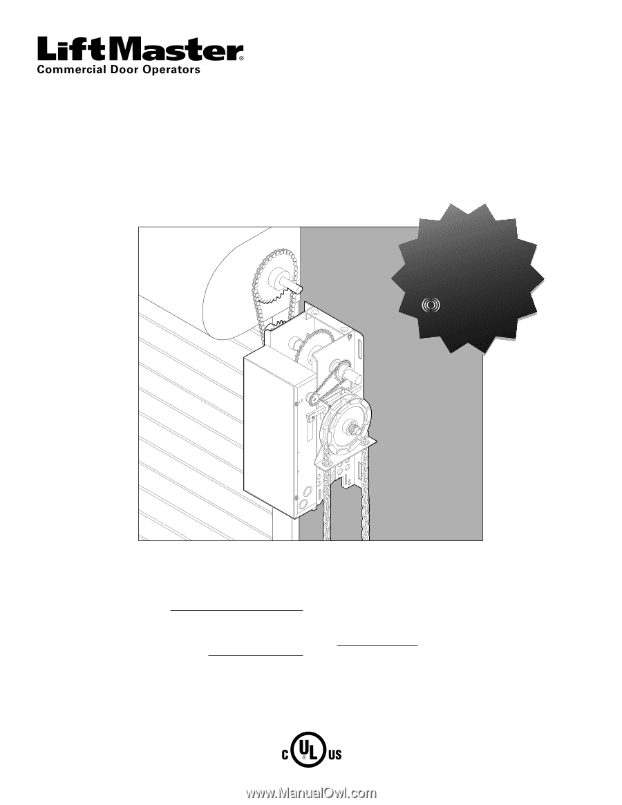
OPERATOR SPECIFICATIONS WEIGHTS AND DIMENSIONS MODELS MH, MJ, AND MHS Hanging Weight: 60-70 LBS. (27.22-31.75 kg) 12.69 03 cm) 9.19" (23.34 cm) Hand Chain Wheel present with Model MH only. 7" (17.78 cm) MODEL MGJ ONLY Hanging Weight: 60 LBS. (27.22 kg) 9.196" (23.36 cm) 12.62" (32.05 cm) 12 - LiftMaster MGJ | Installation Manual - Page 6
: MH Floor level chain hoist for manual chain hoist operation. MJ Floor level disconnect for manual operation. MHS . . . . Both MH and MJ type disconnects described above. MGJ Floor level disconnect for manual operation. ENTRAPMENT PROTECTION: LiftMaster Monitored Entrapment Protection (LMEP - LiftMaster MGJ | Installation Manual - Page 7
For MH and MHS models with manual hoist hand chain systems, the handing of the operator must be determined at the time of order. The handing is indicated by last letter of the model name (R or L). The illustration shown is a right-handed operator for models MJ and MHS series only. Left-handed - LiftMaster MGJ | Installation Manual - Page 8
or door manufacturer). The optimum distance between the door shaft and operator drive shaft is 12-15 inches. WALL MOUNT SHELF OR BRACKET MOUNTING Operator Drive Shaft Door Shaft Optimum Distance 12"-15" Door Shaft Operator Drive Shaft Optimum Distance 12"-15" Optional Mounting Bracket. See - LiftMaster MGJ | Installation Manual - Page 9
until chain is taut (not tight). If chain is too tight, it may cause damage to operator. Door Sprocket Operator Drive Sprocket Door Sprocket Key 6 Keep door sprocket and operator door sprocket aligned. If sprockets are not aligned, they may cause premature wear on the chain. Door Set Screw - LiftMaster MGJ | Installation Manual - Page 10
the manual chain hoist that also electrically disables the operator controls. MODELS MJ AND MGJ ONLY 1 Secure keyhole bracket to wall 4 feet above the floor. 1 Secure chain retaining bracket to wall 4 feet above the floor. 2 Wrap hand chain around hand chain wheel and through chain guide. Keyhole - LiftMaster MGJ | Installation Manual - Page 11
and secured, at that time the unit may be returned to service. • Disconnect power at the fuse box BEFORE proceeding. Operator MUST be properly grounded and connected in accordance with local electrical codes. The operator should be on a separate fused line of adequate capacity. • ALL electrical - LiftMaster MGJ | Installation Manual - Page 12
is visible from the control. door. To prevent possible SERIOUS INJURY or DEATH from a closing • NEVER permit children to operate or play with door control door: push buttons or remote controls. • Install door control within sight of door, out of reach of • Activate door ONLY when it can be - LiftMaster MGJ | Installation Manual - Page 13
TYPICAL INSTALLATION INSTALL 3-BUTTON CONTROL STATION 4 Connect wires to the control station and replace the control station cover. Power 5 Fasten the entrapment warning placard next to the control station. AUX AANUT X ANT AUX ANT ^^^^ TTC LEARN STOP CLOSE OPEN LEDD14 1 2 3 4 5 6 7 - LiftMaster MGJ | Installation Manual - Page 14
SERVICEABLE PARTS. WARNING Tested to Comply with FCC Standards FOR HOME OR OFFICE USE. Operation INSTRUCTIONS. 2. ALWAYS keep remote controls out of reach of children. NEVER permit children to operate or play with door control push buttons or remote If possible, use manual release handle to disengage - LiftMaster MGJ | Installation Manual - Page 15
retaining plate is released, verify that the retaining plate is fully seated with the notches of the limit nut. ADJUST THE CLUTCH FOR MODELS MJ, MH, AND MHS ONLY 1 Apply power to operator. 2 Turn clutch nut to release tension. 3 Re-tighten nut until there is just enough tension to permit smooth - LiftMaster MGJ | Installation Manual - Page 16
disabled. For D1, C2, and E2 wiring the installation of an entrapment device is recommended. AVERTISSEMENT • LiftMaster Monitored Entrapment Protection devices are for use with LiftMaster Commercial Door Operators ONLY. Use with ANY other product voids the warranty. • If an edge sensor is being used - LiftMaster MGJ | Installation Manual - Page 17
ENTRAPMENT PROTECTION INSTALL THE PHOTOELECTRIC SENSORS The following instructions show recommended assembly of the bracket(s) and "C" wrap based on the wall installation of the photoelectric sensors on each side of the door or on - LiftMaster MGJ | Installation Manual - Page 18
. Wing Nut "C" Wrap Wire Indicator Light 1/4"-20x1-1/2" Hex Bolt Sensor Secure wire with insulated staples Bell Wire Connect wire to Operator Photoelectric Sensor 6" (15 cm) max. above floor Invisible Light Beam Protection Area Photoelectric Sensor 6" (15 cm) max. above floor ANT X ANT - LiftMaster MGJ | Installation Manual - Page 19
2 3 DESCRIPTION Open Button Close Button Stop Button FUNCTION Open Door Close Door Stop Door 31 5 42 4 Learn Button Programs the remote controls and performs additional programming 5 Timer-to-Close Button Programs the Timer-to-Close 6 Purple Wire Antenna Primary Antenna 7 Auxiliary Antenna - LiftMaster MGJ | Installation Manual - Page 20
in standard C2 wiring type (factory default). LIFTMASTER MONITORED ENTRAPMENT PROTECTION (LMEP) DEVICE IS RECOMMENDED. A LiftMaster Entrapment Protection (LMEP) device is required for any momentary contact to close mode of operation including B2, TTC and remote controls. NOTES: • The LED on the - LiftMaster MGJ | Installation Manual - Page 21
Monitored Entrapment Protection Device: 1 Press and hold the LEARN and STOP buttons until the LED goes out (approximately 3 seconds). REMOTE CONTROLS MODE B2 B2 with TTC C2 OPEN X X X RADIO OPERATION CLOSE X X (3-button remote) STOP X X X 21 REVERSE WHILE CLOSING X X X TTC RESET X when open - LiftMaster MGJ | Installation Manual - Page 22
315 MHz radio receiver permits as many as 20 Security✚® remote controls or dip switch remote controls in any combination. LMEP1 LMEP2 COM INTRLK STOP CLOSE enables the operator to close from the open limit after a preset time, adjustable from 5 to 60 seconds. Requires LiftMaster Monitored - LiftMaster MGJ | Installation Manual - Page 23
• Be sure you have read and understand all safety instructions included in this manual. • Be sure the owner or person(s) responsible for operation of the door have read and understand the safety instructions, know how to EMENT AVERTISSEMENT electrically operate the door in a safe manner and how to - LiftMaster MGJ | Installation Manual - Page 24
case of emergency or power failure. Refer to the appropriate instructions below for your model operator. MENT AVERTISSEMENT MODEL MH These operators are equipped with a manual hoist. An electrical MODELS MJ AND MGJ This operator has a floor level disconnect chain to disconnect the interlock will - LiftMaster MGJ | Installation Manual - Page 25
➤ Call Technical Support for assistance. A) Clutch slipping ➤ Adjust clutch, see ADJUSTMENT section. B) Brake not releasing (if present) ➤ Verify brake assembly operation and wiring. OPERATOR MOVES IN THE WRONG DIRECTION DOOR DRIFTS AFTER OPERATOR STOPS C) Door operation problem OPEN and CLOSE - LiftMaster MGJ | Installation Manual - Page 26
TROUBLESHOOTING The status of the operator can be determined by counting the number of flashes of the LED on the logic board. # OF LED FLASHES 1 2 3 4 5 6 7 DIAGNOSTIC LED TABLE STATUS FIX System OK. Operating in C2 mode None System OK. Operating operator can travel. Call Technical Support - LiftMaster MGJ | Installation Manual - Page 27
Remote Control: Open/Close/Stop functionality. Includes visor clip. CPS-UN4 Commercial Protector System: LiftMaster : For 1-1/2" shafts For Jackshaft Type Operators 65ME1234 Miller ME123 4-Wire Monitored . May be welded. For use with MJ, MGJ, and MH operators. ANTENNA EXT-ANT Antenna: External kit - LiftMaster MGJ | Installation Manual - Page 28
When adding accessories, install them one at a time and test each one after it is added to ensure proper installation and operation with the Commercial Door Operator. 3 BUTTON STATION OR 3 POSITION KEYSWITCH WITH SPRING RETURN TO CENTER AND STOP BUTTON STANDARD 2 OR MORE KEY LOCKOUT 7635 7635
-
 1
1 -
 2
2 -
 3
3 -
 4
4 -
 5
5 -
 6
6 -
 7
7 -
8
-
9
-
10
-
11
-
12
-
13
-
14
-
15
-
16
-
17
-
18
-
19
-
20
-
21
-
22
-
23
-
24
-
25
-
26
-
27
-
28
 |
 |
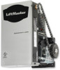
MEDIUM DUTY DOOR OPERATOR
MODELS MJ5011U, MH5011U, MHS5011U, & MGJ5011U
INSTALLATION MANUAL
NOT FOR RESIDENTIAL USE
Now with
Built in
Radio Receiver
315 MHz
Now with
Built in
Radio Receiver
315 MHz
Now with
Built in
Radio Receiver
315 MHz
Now with
Built in
Radio Receiver
315 MHz
Now with
Built in
Radio Receiver
315 MHz
Now with
Built in
Radio Receiver
315 MHz
Your model may look different than the model illustrated in this manual.
THIS PRODUCT IS TO BE
INSTALLED AND SERVICED BY A
TRAINED DOOR SYSTEMS
TECHNICIAN ONLY.
Visit www.liftmaster.com to locate a
professional installing dealer in your area.
Serial #
(located on electrical box cover)
Installation Date
2 YEAR WARRANTY
OPERATOR RATING:
12 cycles per hour,
50 cycles per day; maximum