LiftMaster MH MJ (BLACK LINE) Manual - Page 7
Power Wiring Connections
 |
View all LiftMaster MH manuals
Add to My Manuals
Save this manual to your list of manuals |
Page 7 highlights
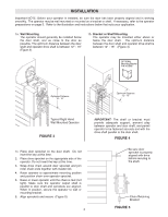
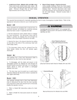
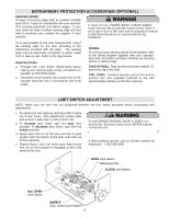
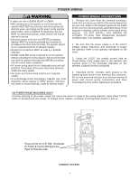
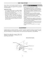
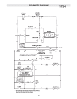
WARNING POWER WIRING WARNING To reduce the risk of SEVERE INJURY or DEATH: • ANY maintenance to the operator or in the area near the operator MUST NOT be performed until disconnecting the electrical power and locking-out the power via the operator power switch. Upon completion of maintenance the area MUST be cleared and secured, at that time the unit may be returned to service. • Disconnect power at the fuse box BEFORE proceeding. Operator MUST be properly grounded and connected in accordance with local electrical codes. The operator should be on a separate fused line of adequate capacity. • All electrical connections MUST be made by a qualified individual. • DO NOT install ANY wiring or attempt to run the operator without consulting the wiring diagram. We recommend that you install an optional reversing edge BEFORE proceeding with the control station installation. • ALL power wiring should be on a dedicated circuit and well protected. The location of the power disconnect should be visible and clearly labeled. • ALL power and control wiring must be run in separate conduit. • To avoid damage to door and operator, make ALL door locks inoperative. Secure locks(s) in "OPEN" position. If the door lock needs to remain functional, install an interlock switch. POWER WIRING CONNECTIONS 1. Remove the cover from the electrical enclosure. Inside this enclosure you will find the wiring diagram(s) for your unit. Refer to the diagram (glued on the inside of the cover) for all connections described below. If this diagram is missing, call the number on the back of this manual. DO NOT INSTALL ANY WIRING OR ATTEMPT TO RUN THIS OPERATOR WITHOUT CONSULTING THE WIRING DIAGRAM. 2. Be sure that the power supply is of the correct voltage, phase, frequency, and amperage to supply the operator. Refer to the operator nameplate on the cover. 3. Using the 1-1/16" dia conduit access hole as shown below, bring supply lines to the operator and connect wires to the terminals indicated on the WIRING CONNECTIONS DIAGRAM. 4. Important NOTE: Connect earth ground to the chassis ground screw in the electrical box enclosure. Do not turn power on until you have finished making all power and control wiring connections and have completed the limit switch adjustment procedure. ON THREE PHASE MACHINES ONLY! Incorrect phasing of the power supply will cause the motor to rotate in the wrong direction (open when CLOSE button is pressed and vice-versa). To change motor rotation, exchange incoming power leads L1 and L2. Three (3) 7/8" & 1-1/6" DIA. Knockouts for Power & Control Wiring access (Near & Opposite side) CONDUIT ACCESS 7
-
 1
1 -
 2
2 -
 3
3 -
 4
4 -
 5
5 -
 6
6 -
 7
7 -
 8
8 -
 9
9 -
 10
10 -
 11
11 -
 12
12 -
13
-
14
-
15
-
16
-
17
-
18
-
19
-
20
-
21
-
22
-
23
-
24
 |
 |
