LiftMaster MH MJ (BLACK LINE) Manual - Page 8
Control Wiring, Mount Warning Notice
 |
View all LiftMaster MH manuals
Add to My Manuals
Save this manual to your list of manuals |
Page 8 highlights
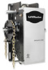
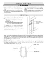
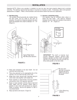
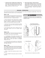
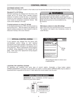
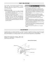
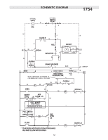
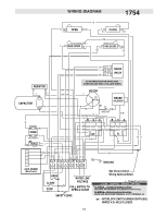
CONTROL WIRING DETERMINE WIRING TYPE Refer to the wiring diagram located on the inside cover the electrical box to determine the type of control wiring. Standard C2 or B2 Wiring Standard operators are shipped from the factory with jumper set for C2 wiring, which requires constant pressure on button to close the door. If momentary contact on close direction is desired (B2 wiring) you must include an entrapment protection device. See close control settings to the right. WARNING To prevent possible SERIOUS INJURY or DEATH, install CAUTION reversing sensors when the 3-button control station is out of sight of the door or ANY other control (automatic or manual) is used. Reversing devices are recommended for ALL installations. Constant pressure on close (C2 wiring) In the electrical enclosure, a RED wire was placed on terminal block #12. With this setting, the operator will require constant pressure on close control in order to keep door moving in the close direction. Momentary contact on close (B2 wiring) Move RED wire from terminal block #12 to terminal #2. The operator will require only momentary contact to close the door. SPECIAL CONTROL WIRING If your operator was shipped from the factory with non-standard control wiring or with optional accessories that require addition instructions, refer to the wiring diagram(s) indicated in the special control wiring data box. When a replacement wiring diagram is present, wiring diagrams in this manual will not apply. Refer only to the replacement wiring diagram for all connections. SPECIAL CONTROL WIRING DATA This Operator has Control Wiring. SUPPLEMENTAL WIRING DIAGRAM(S) REPLACEMENT WIRING DIAGRAM WIRING Wiring Type Note: Supplemental Wiring Diagrams are to be used in addition to 1753 or 1754. Replacement Wiring Diagram is to be used in place of 1753 or 1754. Wiring Diagram label on inside cover of electrical box LOCATING THE CONTROL STATION All operators are supplied with some type of control station. Generally a three button station (OPEN/CLOSE/STOP) is provided. A two-position key switch or control station (OPEN/CLOSE) may be added or substituted when requested at the time of order. Mount the control station near the door. MOUNT WARNING NOTICE IMPORTANT: Mount WARNING NOTICE beside or below the push button station. Control Station Push Buttons OPEN CLOSE STOP WARNING TO PREVENT ENTRAPMENT DO NOT START DOOR DOWNWARD UNLESS DOORWAY IS CLEAR WARNING Notice 8
-
 1
1 -
2
-
 3
3 -
 4
4 -
 5
5 -
 6
6 -
 7
7 -
 8
8 -
 9
9 -
 10
10 -
 11
11 -
 12
12 -
 13
13 -
14
-
15
-
16
-
17
-
18
-
19
-
20
-
21
-
22
-
23
-
24
 |
 |