LiftMaster RSW12UL Installation Manual
LiftMaster RSW12UL Manual
 |
View all LiftMaster RSW12UL manuals
Add to My Manuals
Save this manual to your list of manuals |
LiftMaster RSW12UL manual content summary:
- LiftMaster RSW12UL | Installation Manual - Page 1
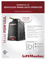
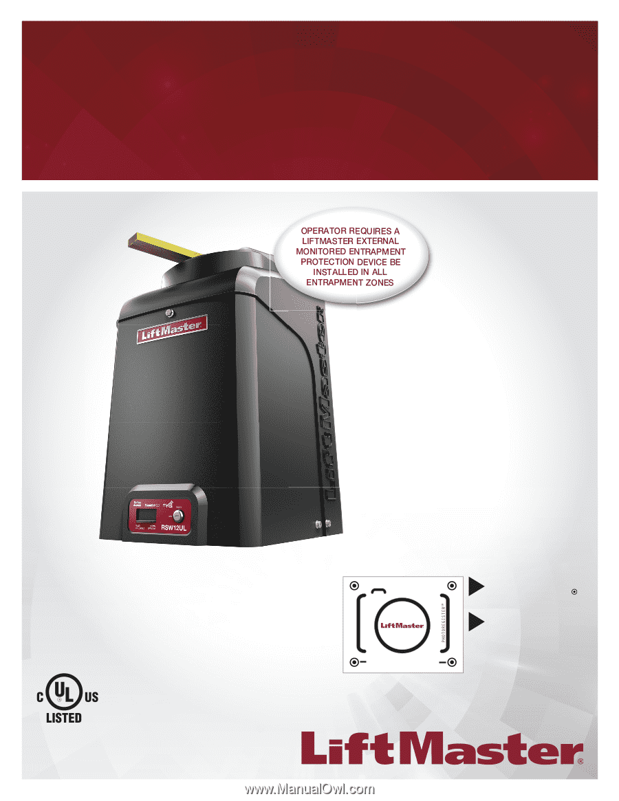
RESIDENTIAL DC VEHICULAR SWING GATE OPERATOR INSTALLATION MANUAL Model RSW12UL LiftMaster 300 Windsor Drive Oak Brook, IL 60523 • THIS PRODUCT IS TO BE INSTALLED AND SERVICED BY A TRAINED GATE SYSTEMS TECHNICIAN ONLY. • This model is for use on vehicular passage gates ONLY and not intended for - LiftMaster RSW12UL | Installation Manual - Page 2
NOTE: • BEFORE attempting to install, operate or maintain the operator, you must read and fully understand this manual and follow all safety instructions. • DO NOT attempt repair or service of your gate operator unless you are an Authorized Service Technician. MECHANICAL ELECTRICAL WARNING: This - LiftMaster RSW12UL | Installation Manual - Page 3
swing gate operator will operate only after installation of a minimum of two independent* monitored entrapment protection devices in either the open when the gate is not moving. l KEEP GATES PROPERLY MAINTAINED. Read the owner's manual. Have a qualified service person make repairs to gate hardware. - LiftMaster RSW12UL | Installation Manual - Page 4
in a location so that enough clearance is supplied between the gate and adjacent structures when opening and closing to reduce the risk of entrapment. Swinging gates shall not open into public access areas. 7. The gate must be properly installed and work freely in both directions prior to the - LiftMaster RSW12UL | Installation Manual - Page 5
vertical plane, when a 3.1.1 Gates shall be designed, constructed and installed so as not to create an entrapment area between the gate and the supporting gate is detached from the supporting hardware. structure or other fixed object when the gate moves toward the fully open position, subject to - LiftMaster RSW12UL | Installation Manual - Page 6
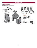
INTRODUCTION Carton Inventory NOT SHOWN: Documentation packet and hardware bag 6 - LiftMaster RSW12UL | Installation Manual - Page 7
ON + SW (switched) Solar Power Max 12 Vdc at 30 watts max. Maximum Gate Weight/Length 400 lbs. (181.4 kg)/16 ft. (4.9 m) 600 lbs. ( open and up to 4 edge sensors using wireless edge sensor kit model LMWEKITU . *Travel time and range are affected by A and B mounting dimensions, see INSTALLATION - LiftMaster RSW12UL | Installation Manual - Page 8
needs. Check your gate Gate MUST be level. Gate and gate post MUST be plumb. Gate MUST have a smooth bottom edge, no protrusions should exist. Remove ANY/ALL wheels from the bottom of gate. Gate MUST NOT hit or drag across ground Gate MUST swing freely and be supported entirely by its hinges - LiftMaster RSW12UL | Installation Manual - Page 9
Location for Concrete Pad and Operator For compact installation refer to the Appendix for installation steps 1-4, page 39. DO NOT run the operator until instructed. The illustration below shows the recommended dimensions for a standard installation. If these dimensions are not applicable for your - LiftMaster RSW12UL | Installation Manual - Page 10
INSTALLATION Chart Installation Refer to the illustration to determine the measurements and location of the concrete pad. Dimension (A) thru (E) are from the center of one pivot point to the center of another pivot point. Caution: If the gate is longer than 18 feet (5.5 m), follow CHART A: A-2. - LiftMaster RSW12UL | Installation Manual - Page 11
Step 2 Concrete Pad and Operator Attachment CHECK the national and local building codes before installation. NOTE: When lifting the operator use the handle to avoid damaging the operator 1. Install the electrical conduit. 2. Pour a concrete pad (reinforced concrete is recommended). The concrete pad - LiftMaster RSW12UL | Installation Manual - Page 12
in place while determining the correct measurements. 1. Close the gate and measure the distance of the operator arm from the gate bracket to the output shaft center. This distance is E. 2. Open the gate 90° (do not allow arms to scissor when open). Measure both sections of the arm (D and C). The arm - LiftMaster RSW12UL | Installation Manual - Page 13
INSTALLATION Step 5 Secure the Operator Arm Once the operator arm measurements are verified: 1. Weld the gate bracket to the gate. 2. Weld the short arm section. 3. Weld the long arm section. 4. Remove the set screws from the arm. NOTE: Completely weld around the outer tubing and - LiftMaster RSW12UL | Installation Manual - Page 14
the open and close gate cycles. l LiftMaster monitored external entrapment protection devices MUST be used with LiftMaster operators to meet UL325 requirements, see Accessories. l Test ALL entrapment protection devices after completing installation of the operator. For testing instructions, refer - LiftMaster RSW12UL | Installation Manual - Page 15
entrapment protection for the close direction. When an obstruction is sensed during gate closing the gate will open to the full open position and resets the Timer-to-Close. This input will be disregarded during gate opening. CLOSE EDGE (2 Terminals) The CLOSE EDGE input is for edge sensor entrapment - LiftMaster RSW12UL | Installation Manual - Page 16
destroy its integrity, replace it with a single wire length. 1. Install the earth ground rod within 3 feet (.9 m) of the operator that time the unit may be returned to service. l ALL power wiring should be on wire harness (Model K94-37236). For dual gate applications, power will have to be connected - LiftMaster RSW12UL | Installation Manual - Page 17
INSTALLATION Power wiring 1. Turn off the AC power from the main power source circuit to the operator. 33AH battery To use a 33AH battery in place of the 7AH battery, follow the instructions below. The 33AH application requires the 33AH wire harness (Model K94-37236). 1. Unplug the transformer. 2. - LiftMaster RSW12UL | Installation Manual - Page 18
INSTALLATION Step 9 Dual Gate Setup There are two options for dual gate communication: wired or wireless. Follow the directions according to your application. Do not use wired and wireless communication simultaneously. Wired dual gate 4. Press and release the OPEN test button to assign this operator - LiftMaster RSW12UL | Installation Manual - Page 19
INSTALLATION DELAY switch is used only with dual gate applications and serves two functions: l BIPART DELAY SWING GATE APPLICATIONS: The BIPART DELAY is will delay from the close limit when opening and be the first to close from the open limit. SLIDE GATE APPLICATIONS: Not applicable, set to OFF. - LiftMaster RSW12UL | Installation Manual - Page 20
Step 10 Install the cover Before installing the cover, follow the instructions in the Adjustment section to adjust the limits and force. The operator cover consists of two pieces: a tab 180 degrees, then secure with the screw. The access door can now be locked. The basic installation is complete. 20 - LiftMaster RSW12UL | Installation Manual - Page 21
a 3-button remote control programmed to OPEN, CLOSE, and STOP. NOTE: The TEST buttons on the control board will not work until the limits have been set and the required entrapment protection devices are installed. Initial Limits and Force Adjustment For dual gate applications the limits will have to - LiftMaster RSW12UL | Installation Manual - Page 22
injury to a person. The force setting is the same for both the open and close gate directions. 1. Open and close the gate with the TEST BUTTONS. 2. If the gate stops or reverses before reaching the fully open or closed position, increase the force by turning the force control slightly clockwise - LiftMaster RSW12UL | Installation Manual - Page 23
1. Make sure gate/door is closed. 2. Give the operator an OPEN command. 3. Within 30 seconds, when the gate/door is at the open limit press and installation. This equipment generates, uses and can radiate radio frequency energy and, if not installed and used in accordance with the instructions - LiftMaster RSW12UL | Installation Manual - Page 24
shown by the LiftMaster Internet Gateway app will be either "open" or "closed". The gate operator can then be controlled through the LiftMaster Internet Gateway only be programmed to ONE gate operator (see the KPW5/KPW250 manual for complete programming instructions). The Constant Pressure Override - LiftMaster RSW12UL | Installation Manual - Page 25
will display as "SG" followed by a "12" which indicates the operator type as RSW12UL. The firmware version will show after the operator type, example "1.2". 12 BACKDRIVE Switch: Set to MANUAL will allow the gate to be manually pushed open or closed if there is a loss of AC and battery power. Set to - LiftMaster RSW12UL | Installation Manual - Page 26
Disconnect Press the reset switch to RESET/DISCONNECT. Release the handle on the operator arm to allow the gate to be opened and closed manually. On a dual gate application the handle must be released on both operators. To resume normal function tighten the handle by pushing it down. Reset Switch - LiftMaster RSW12UL | Installation Manual - Page 27
command the gate to open. l Opens a closing gate and holds open an open gate, if maintained, pauses Timer-to-Close at OPEN limit. SHADOW (2 Terminals) This input is used for external shadow loop detector when loop is positioned under the swing of the gate. l Holds open gate at open limit l Only - LiftMaster RSW12UL | Installation Manual - Page 28
safeties and resets alarm condition). If maintained, pauses Timer-to-Close at OPEN limit. Opens a closing gate and holds open an open gate (within line-of-sight). l CLOSE and COM: Closes an open gate. Hard close (maintained switch overrides external safeties and resets alarm condition within - LiftMaster RSW12UL | Installation Manual - Page 29
INSTRUCTIONS. l Test the gate operator monthly. The gate manual. national and local electrical codes. NOTE: The operator should be on Have a qualified service person make repairs to gate hardware. a separate fused line of adequate capacity. l ALL maintenance MUST be performed by a LiftMaster - LiftMaster RSW12UL | Installation Manual - Page 30
is low. Batteries do not perform well in extremely cold temperatures. For best performance, the batteries should be replaced every 3 years. Use only LiftMaster part 29-NP712 for replacement batteries. The batteries contain lead and need to be disposed of properly. The operator comes with one 7AH - LiftMaster RSW12UL | Installation Manual - Page 31
TROUBLESHOOTING To protect against fire and electrocution: l DISCONNECT power (AC or solar and battery) BEFORE installing or servicing operator. For continued protection against fire: l Replace ONLY with fuse of same type and rating. Diagnostic Codes NOTE: When cycling or disconnecting power (ac/ - LiftMaster RSW12UL | Installation Manual - Page 32
then re-learn the second operator. Review monitored entrapment protection device connections. This swing gate operator will operate only after installation of a minimum of one external safety device in either the open or close direction. Check wired input on main control board; check for alignment - LiftMaster RSW12UL | Installation Manual - Page 33
TROUBLESHOOTING Code 69 70 71 72 73 74 75 80 81 82 83 84 91 93 99 Meaning Wireless edge triggered CLOSE EYE/INTERRUPT triggered, causing reversal, preventing close, or resetting TTC CLOSE EDGE triggered, causing reversal, NO preventing close, or canceling TTC OPEN are not supported. Make sure - LiftMaster RSW12UL | Installation Manual - Page 34
TROUBLESHOOTING Control Board LEDs INPUT OFF POWER ON STATUS LEDS OFF BLINK (2 The timer is paused blinks per second) GATE MOVING FASTEST BLINK (8 The timer is canceled blinks per second) OFF The gate is stopped ON The gate is opening or closing BATT LOW ACC PWR OVLD MEDIUM BLINK (1 - LiftMaster RSW12UL | Installation Manual - Page 35
Replace defective control board a. Use manual disconnect, manually move gate, and ensure gate moves easily limit to limit. Repair gate as needed. b. Gate must move easily and freely through its entire range, limit to limit. Repair gate as needed. Gate does not fully open or fully close when setting - LiftMaster RSW12UL | Installation Manual - Page 36
TROUBLESHOOTING SYMPTOM Gate closes, but will not open. Obstruction in gate's path does not cause gate to stop and reverse. Photoelectric sensor does not stop or reverse gate. Edge Sensor does not stop or reverse gate with a command. On dual-gate system, incorrect gate opens first or closes first. - LiftMaster RSW12UL | Installation Manual - Page 37
TROUBLESHOOTING SYMPTOM Accessories connected to Accessory power not working correctly, turning off control board a. Add more solar panels b. Reduce the accessory power draw by using LiftMaster low power accessories c. Replace batteries d. Relocate the solar panels away from obstructions (trees - LiftMaster RSW12UL | Installation Manual - Page 38
APPENDIX Dual Gate Settings NOTE: We recommend that all installation. Compact Installation The illustration is an example of a compact installation. If the operator arm will hit an obstruction when the gate is in the open position, refer to LiftMaster.com for compact installation instructions - LiftMaster RSW12UL | Installation Manual - Page 39
APPENDIX Step 1 Determine Location for Concrete Pad and Operator Compact Installation Only DO NOT run the operator until instructed. Refer to the illustration to determine the measurements and location of the concrete pad. NOTE: When lifting the operator use the handle to avoid damaging - LiftMaster RSW12UL | Installation Manual - Page 40
hold the arm in place while determining the correct measurements. Step 4 Position the Gate Bracket Compact Installation Only NOTE: It may be necessary to attach horizontal reinforcement to the gate before attaching the gate bracket. Use the set screws on the arm to temporarily hold the arm in - LiftMaster RSW12UL | Installation Manual - Page 41
the given zones as shown on the map below. Local geography and weather conditions may require additional solar panels. Solar powered gate operator installations are not supported in northern climates due to cold weather and a reduced number of hours of sunlight during the winter months. The cycles - LiftMaster RSW12UL | Installation Manual - Page 42
APPENDIX Solar usage guide Typical System Standby Battery Current Consumption (mA) System voltage Main board with no radios programmed One or more LiftMaster® remote controls programmed MyQ® device or wireless dual gate programmed Expansion board Per loop detector LOOPDETLM (up to 3 loop detectors - LiftMaster RSW12UL | Installation Manual - Page 43
m) Chart assumes: copper wire, 65°C, 5% drop, 30V nominal Installation Solar panel(s) MUST be installed facing south. Use a compass to determine direction. Below are general instructions for installing the solar panel(s). Your installation may vary slightly depending on the solar panel purchased - LiftMaster RSW12UL | Installation Manual - Page 44
APPENDIX Wire the Batteries Solar panel applications require the Solar Harness Kit model K94-37236, see Accessories. Wire the Solar Panels Proceed to the Dual Gate section (if applicable) or proceed to the Adjustment section. 44 - LiftMaster RSW12UL | Installation Manual - Page 45
again to set the close limit. 8. Cycle the gate open and close. This automatically sets the force. When limits are set properly the operator will automatically exit limit setting mode. Refer to the Adjustment section and follow the instructions for Fine Tune the Force and Obstruction Test . Perform - LiftMaster RSW12UL | Installation Manual - Page 46
To protect against fire and electrocution: l DISCONNECT power (AC or solar and battery) BEFORE installing or servicing operator. For continued protection against fire: l Replace ONLY with fuse of same type and rating. WIRING DIAGRAM 46 - LiftMaster RSW12UL | Installation Manual - Page 47
REPAIR PARTS NOT SHOWN K94-37336 Wiring Harness with product ID assembly K94-37230 Battery Harness (for 7AH batteries) K94-37236 Battery Harness (for 33AH batteries) 47 - LiftMaster RSW12UL | Installation Manual - Page 48
profile ends kit (10 pair) Model S50E Remote Controls LiftMaster offers a variety of LiftMaster remote controls to satisfy your application needs. Single-button 890MAX Security+ 2.0® learning remote controls One button can control a gate operator and the other (s) can control garage door(s). It can - LiftMaster RSW12UL | Installation Manual - Page 49
extension kit allows the antenna to be remotely installed. Model 86LM Commercial access control receiver Access control LiftMaster low power accessory. Model LD7LP Vehicle sensing probe The vehicle sensing probe is buried in the ground and can detect a car as it approaches and will then open the gate - LiftMaster RSW12UL | Installation Manual - Page 50
LiftMaster warrants to the first purchaser of this product, for the structure in which this product is originally installed service center for warranty repair. You will be advised of shipping instructions when you call. Please include a brief description of the problem WITH THE SALE OF THIS - LiftMaster RSW12UL | Installation Manual - Page 51
NOTES 51 - LiftMaster RSW12UL | Installation Manual - Page 52
300 Windsor Drive Oak Brook, IL 60523 LiftMaster.com © 2018, The Chamberlain Group, Inc. - All Rights Reserved 01-39378B
-
 1
1 -
 2
2 -
 3
3 -
 4
4 -
 5
5 -
 6
6 -
 7
7 -
8
-
9
-
10
-
11
-
12
-
13
-
14
-
15
-
16
-
17
-
18
-
19
-
20
-
21
-
22
-
23
-
24
-
25
-
26
-
27
-
28
-
29
-
30
-
31
-
32
-
33
-
34
-
35
-
36
-
37
-
38
-
39
-
40
-
41
-
42
-
43
-
44
-
45
-
46
-
47
-
48
-
49
-
50
-
51
-
52
 |
 |
Model
RSW12UL
•
THIS PRODUCT IS TO BE INSTALLED AND
SERVICED BY A TRAINED GATE SYSTEMS
TECHNICIAN ONLY.
•
This model is for use on vehicular passage
gates ONLY and not intended for use on
pedestrian passage gates.
•
This model is intended for use in Class I and II
vehicular swing gate applications.
•
Visit LiftMaster.com to locate a professional
installing dealer in your area.
•
This gate operator is compatible with MyQ
®
and Security+ 2.0
®
accessories.
LiftMaster
300 Windsor Drive
Oak Brook, IL 60523
RESIDENTIAL DC
VEHICULAR SWING GATE OPERATOR
INSTALLATION MANUAL
Access installation and technical support
guides or register this product
Send it in
by texting the
photo to 71403.
Take a photo
of the camera
icon including the points (
).
1.
2.
•
•
•
•
•
•
Acce
RSW12ULTECH