LiftMaster SL3000UL3 Owners Manual - Page 42
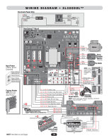
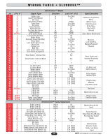
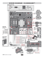
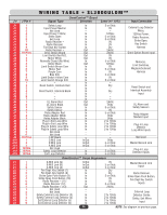
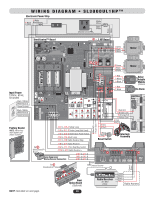
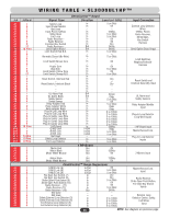
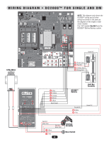
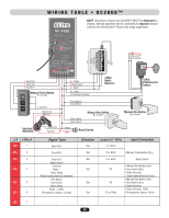
Wiring Table SL3000UL1HP, See diagram on previous
 |
View all LiftMaster SL3000UL3 manuals
Add to My Manuals
Save this manual to your list of manuals |
Page 42 highlights
J # J Pin # J1 1 J1 2 J1 3 J1 4 J1 5 J1 6 J1 7 J1 8 J1 9 J1 10 J2 10 Pins J3 1 J3 2 J3 3 J3 4 J3 5 J3 6 J3 7 J3 8 J3 9 J3 10 J5 1 J5 2 J5 3 J5 4 J5 5 J5 6 J5 7 J6 1 J6 2 J6 3 J6 4 J7 1 J7 2 J7 3 J8 1 J8 2 J8 3 J8 4 J8 5 J8 6 J9 16 Pins J10 1 J10 2 J10 3 J11 10 Pins J12 10 Pins J13 10 Pins J1 1 J1 2 J1 3 J1 4 J1 5 J1 6 J1 1 J1 2 J1 3 J2 1 J2 2 J2 3 J2 4 J2 5 J2 6 J2 7 J3 1 J3 2 J3 3 J3 4 J3 5 J3 6 WIRING TABLE • SL3000UL1HP™ OmniControl™ Board Signal Type Safety Loop Input Power Neutral Not Used Input Power 120Vac Strike Open Exit Loop Radio Receiver - Radio Receiver Fire Dept Key Switch Radio Receiver + Omni Option Board Limit Switch Red N.O. - Normally Closed (No Wire) - Limit Switch Brown Com - Purple Com Blue N.O. Limit Switch Yellow Com Limit Switch Orange N.O. - Reset Switch, Interlock Red - Reset Switch, Interlock Black - - - UL Alarm Red UL Alarm Black Safety Sensor Safety Sensor Relay Adapter Red Relay Adapter White Relay Adapter Black Plug-In Exit Loop Wire Plug-In Exit Loop Wire Plug-In Safety Loop Wire Plug-In Safety Loop Wire Plug-In Center Loop Wire Plug-In Center Loop Wire 1 HP Board G M/S Link B M/S Link A M/S Link Not Used Safety Loop Detector Exit Loop Detector Direction In In - In In In In In In Out Out In - In - In - In In In In In In In In In In In Out Out In In In In In In In In In In In In In/Out In/Out In/Out - In In Level (+/- 10%) 5 or 0Vdc 0V - 120Vac 5 or 0Vdc 5 or 0Vdc 0V 0V Dry 24Vdc 24Vdc 5 or 0Vdc - 5 or 0Vdc - 0V - 0V 5 or 0Vdc 0V 5 or 0Vdc - Dry - Dry - - - 24Vdc 0Vdc 5 or 0Vdc 0V 5 or 0Vdc 0Vdc 0Vdc 2 to 10Vdc 2 to 10Vdc 2 to 10Vdc 2 to 10Vdc 2 to 10Vdc 2 to 10Vdc 120Vac 0Vdc 5 or 0Vdc 5 or 0Vdc - 5 or 0Vdc 5 or 0Vdc Input Connection External Loop Detector Wires, 120Vac Power, Radio Receiver, Strike Open, Key Switch Harness Omni Option Board Input Limit Switches, Maglock/Solenoid Harness Reset Switch and Interlock Assembly Input UL Alarm and Safety Sensors Relay Adapter Module Input Plug-In Loop Detector Loop Wire Inputs 1 HP Board Input Master/Second Link Plug-In Loop Detector Inputs Motor Red Motor Black Motor White Neutral - Motor Black Motor White Neutral 1 HP Board Out Out Out - Out Out 0V 120Vac 0V - 120Vac 0V 2 Motors Input OmniControl™ Surge Suppressor G M/S Link (G) B M/S Link (B) A M/S Link (A) Fire Dept. Key Switch (7) Fire Dept. Key Switch (8) Strike Open Push Button (9) Strike Open Push Button (10) Radio Receiver - (11) Radio Receiver (12) Radio Receiver + (13) In/Out In/Out In/Out In In In In In In Out 0V 5 or 0Vdc 5 or 0Vdc Dry Dry 5 or 0Vdc 0V 0V 5 or 0Vdc 24Vdc Not Used - Not Used - Safety External Loop Detector (3) In Safety External Loop Detector (4) In Exit External Loop Detector (5) In Exit External Loop Detector (6) In - - 2 to 10Vdc 2 to 10Vdc 2 to 10Vdc 2 to 10Vdc Master/Second Link Input Radio Receiver, Strike Open Push Button, Fire Dept Key Switch Inputs External Loop Detector Center, Safety, Exit Wires Input 40 NOTE: See diagram on previous page.
-
 1
1 -
2
-
3
-
4
-
5
-
6
-
7
-
8
-
9
-
10
-
11
-
12
-
13
-
14
-
15
-
16
-
17
-
18
-
19
-
20
-
21
-
22
-
23
-
24
-
25
-
26
-
27
-
28
-
29
-
30
-
31
-
32
-
33
-
34
-
35
-
36
-
 37
37 -
 38
38 -
 39
39 -
 40
40 -
 41
41 -
 42
42 -
 43
43 -
 44
44 -
 45
45 -
 46
46 -
 47
47 -
48
-
49
-
50
-
51
-
52
 |
 |