LiftMaster SW470 SW490 S3 BOARD Manual
LiftMaster SW470 Manual
 |
View all LiftMaster SW470 manuals
Add to My Manuals
Save this manual to your list of manuals |
LiftMaster SW470 manual content summary:
- LiftMaster SW470 | SW490 S3 BOARD Manual - Page 1
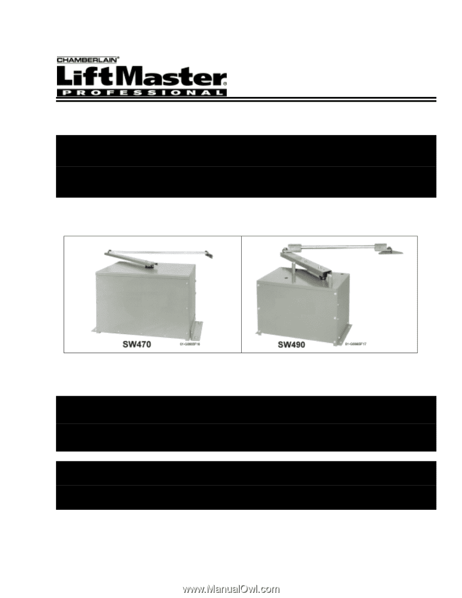
Installation and Maintenance Instructions Medium & Heavy Duty Swing Gate Operators Models: SW470 SW490 Doc 01-G0665 Rev C - LiftMaster SW470 | SW490 S3 BOARD Manual - Page 2
to Close 20 Controls and Accessory Installation 21 Manual Operation and System Check-Out 22 SW470 Manual Gate Operation 22 Preliminary System Check Out 22 Required Maintenance - Normal Usage 23 Troubleshooting 24 SW470 Parts List and Drawing 25 SW470 Exploded View 25 Doc 01-G0665 Rev C - LiftMaster SW470 | SW490 S3 BOARD Manual - Page 3
Contents 3 SW470 Parts List 26 SW490 Parts List and Drawing 27 SW490 Exploded View 27 SW490 Parts List 28 Warranty Policy 30 IMPORTANT! Please leave this manual at the job site, preferably with the end user or facility manager. Read and follow all instructions. This gate operator is intended - LiftMaster SW470 | SW490 S3 BOARD Manual - Page 4
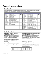
unit, some may be packed separately. PART # 01-G0582 02-401-SP 10-2108-T 10-2109 10-2111 40-3505 80-2103 82-HN38-20 82-SB50-08 84-WH-38 85-FW-38 SW470 DESCRIPTION GATE OPERATIONAL SAFETY INSTRUCTION MANUAL STOP BUTTON ARM CHANNEL EXTENSION ARM GATE BRACKET DORCMA WARNING SIGN BLACK PLASTIC KNOB - LiftMaster SW470 | SW490 S3 BOARD Manual - Page 5
Specifications Model SW470-50 SW490-33 SW490-50 SW490-75 SW490-100 General Information 5 HP Max. Wt. (Lbs.) Max. Gate Width ½ 500 12 FT. 1/3 600 12 FT. ½ 750 16 FT. ¾ 900 19 FT. 1 1000 22 FT. Table 3 Doc 01-G0665 Rev C - LiftMaster SW470 | SW490 S3 BOARD Manual - Page 6
in design. 7 Confirm gate moves freely before installation of operator. 8 Repair or service worn or damaged gate hardware before installation of operator. 9 To avoid installation hazards, review the gate system operation and installation procedures, such as manual disconnect mechanism procedure. 10 - LiftMaster SW470 | SW490 S3 BOARD Manual - Page 7
Disconnect power at service panel before making any electrical connection. 2 Avoid pinch points; be aware of all moving parts. 3 Adjust clutch gate system. 3 Leave Installation and Maintenance Manual and Safety Information with end user. FOR GATE OPERATORS USING NON-CONTACT SENSOR(S) See instruction - LiftMaster SW470 | SW490 S3 BOARD Manual - Page 8
and it is operated. This potential hazard can be averted by placing a screen mesh on the gate to prevent access through the openings. See Figure 2. Photo-Electric Beam Always test Gate Edges and Photo Beams anytime they are adjusted or serviced. Gate Edge on Leading Edge of Gates Doc 01-G0665 - LiftMaster SW470 | SW490 S3 BOARD Manual - Page 9
, adjust or repair the gate prior to operator installation. The gate must be level. ! Double check the size and weight of the gate to make sure that it Calculated using NEC guidelines. Local codes and conditions must be reviewed for suitability of wire installation. Master/Slave units must be installed - LiftMaster SW470 | SW490 S3 BOARD Manual - Page 10
length in feet for 1/3 HP motor 3,100 4,750 14,225 1,950 3,000 8,975 1,225 11,225 7,050 4,425 11,850 7,475 4,700 2,950 8,900 5,625 3,525 2, 225 System Features ACTIVITY LED Steady indication when gate is at either open or close limit. 1 second flash when gate is off a limit in normal operation - LiftMaster SW470 | SW490 S3 BOARD Manual - Page 11
in time delay to close. Either a manual device such as a pushbutton within line of site of the gate and operator or the stop button supplied with the operator must be activated to return the operator to its normal operation. OPEN ONLY CIRCUIT Separate open circuits for line-of-sight devices and out - LiftMaster SW470 | SW490 S3 BOARD Manual - Page 12
expectancy will be greatly reduced. SW470 gate operators have provisions for both post and pad mounting. However, because of the high torque involved in most swing gate installations, pad mounting is the recommended method. NOTE: Instructions are for right hand operator installation. Left hand is - LiftMaster SW470 | SW490 S3 BOARD Manual - Page 13
mounting flanges and should be secured with hex nuts and lockwashers (not provided). It is very important that the operator is level and parallel to the gate. DIMENSION TABLE A B C D SW470 9-3/4" 22-1/2" 24" 8" SW490 16" 28" 32" 8" Table 6 Figure 6 0 1 -G 0 66 5 F2 Doc 01-G0665 Rev - LiftMaster SW470 | SW490 S3 BOARD Manual - Page 14
ONLY Figure 7 01-G0665F20 2 Attach control arm extension to control arm on operator with (2) 3/8-16 x 1" long hex head bolts and lockwashers. Use holes that are appropriate for degree of gate opening required. Figure 8 0 1 -G 0 6 6 5 F3 3 Assemble the (2) extension arm holders, one to the - LiftMaster SW470 | SW490 S3 BOARD Manual - Page 15
arm stops on the operator in the positions appropriate for the installation. Then install the control arm and hub assembly to the operator output shaft. Attach control 11. Be sure to keep the extension arm with spot-faced side up. Use the holes that are appropriate for desired degree of gate opening - LiftMaster SW470 | SW490 S3 BOARD Manual - Page 16
CHANNEL (10-2108-T) Figure 11 Gate Bracket Installation 1 If required, install an angle (2" x 2" x ¼" by others) horizontally on the gate, at the same height as line. Install the gate bracket at the appropriate point on the gate (or angle, if used). As an alternative on the Model SW470 only, (2) 3/8 - LiftMaster SW470 | SW490 S3 BOARD Manual - Page 17
is selected by dip switch #1, pin #2 for left or right hand operation. TO ADJUST CLOSE LIMIT SWITCH TO ADJUST OPEN LIMIT SWITCH 1 Move gate to the desired fully closed position. 1 Move the gate to the desired fully opened position. 2 Loosed set screw on close limit cam. 2 Loosed set screw - LiftMaster SW470 | SW490 S3 BOARD Manual - Page 18
have - L1, L2, L3 and ground. It is very important that operator is properly grounded. IMPORTANT NOTE:On three phase operators the power connections must be properly phased. If they are phased wrong the gate operator will run backwards. To correct this situation, disconnect power a main power source - LiftMaster SW470 | SW490 S3 BOARD Manual - Page 19
19 Figure 16 0 1 -G 06 6 5 F1 1 Switch #1: Operator Programming POLE #1 - SINGLE/CLOSE BUTTON ON = Close button only OFF = Open/Close Button POLE #2 - RIGHT HAND/LEFT HAND ON = Left Hand (gate will open to the left) OFF = Right Hand (gate will open to the right) (Determine hand selection from - LiftMaster SW470 | SW490 S3 BOARD Manual - Page 20
the bottom two pins, or move all pins of SW#2 to ON. IMPORTANT NOTE: When using master/slave, only set the time for the master operator. The slave operator must be set to disabled position (all poles on). Doc 01-G0665 Rev C - LiftMaster SW470 | SW490 S3 BOARD Manual - Page 21
the manual. Installation device instructions - always follow the instructions provided by the manufacturer when installing and adjusting any control device. If these instructions are contrary to the advice given here, call for assistance. WARNING All controls that are to be used to operate the gate - LiftMaster SW470 | SW490 S3 BOARD Manual - Page 22
22 Manual Operation and System Check-Out Manual Operation and System CheckOut SW470 Manual Gate Operation Remove the (2) black plastic knobs which secure the control arm assembly to the operator. The gate will swing freely when the arm assembly is removed. Preliminary System Check Out Before adding - LiftMaster SW470 | SW490 S3 BOARD Manual - Page 23
use only a proper chain lube spray or a lightweight motor oil. Never use grease or silicone spray. F. When servicing, please do some "house cleaning" of the operator and the area around the operator. Pick up any debris in the area. Clean the operator if needed. G. It is suggested that while you are - LiftMaster SW470 | SW490 S3 BOARD Manual - Page 24
24 Troubleshooting Troubleshooting A properly installed SW470 or SW490 operator will operate for many years with a minimum or service maintenance. It is important to note, however, that a binding or defective gate can severely reduce the life of the operator. The gate operation should be checked - LiftMaster SW470 | SW490 S3 BOARD Manual - Page 25
SW470 Parts List and Drawing 25 SW470 Parts List and Drawing SW470 Exploded View Figure 20 Doc 01-G0665 Rev C - LiftMaster SW470 | SW490 S3 BOARD Manual - Page 26
QTY DESCRIPTION FOR 115 VOLT OPERATORS 20-2100 1 MOTOR 29-3530 1 CAPACITOR 74-SW4705011 1 SW470 S3 CONTROL PANEL FOR 230 50/60 HZ VOLT OPERATORS 20-2101-LD 1 MOTOR 74-SW4705021 1 SW470 S3 CONTROL PANEL COMMON PARTS OF THE SW470 02-401-SP (N) 1 STOP BUTTON 03-8024 03-ABDIN-4 07-2101 07 - LiftMaster SW470 | SW490 S3 BOARD Manual - Page 27
SW490 Parts List and Drawing 27 SW490 Parts List and Drawing SW490 Exploded View Figure 21 Doc 01-G0665 Rev C - LiftMaster SW470 | SW490 S3 BOARD Manual - Page 28
PARTS PART NO. STOP BUTTON 19-9024 REVERSING CONTACTOR 24VAC 23-2016 DIN RAIL 23-3001 ARM ASSEMBLY EXTENSION ARM HOLDER SIDE PLATE SWITCH PLATE GATE BRACKET MOUNTING ANGLE HOUSING EXTENSION ARM ARM SHAFT SWITCH BOX COVER SENSOR SUPPORT MASER LINK, #50 2 LIM. SWITCH, AUX.OPEN/CLOSE 1 DPST - LiftMaster SW470 | SW490 S3 BOARD Manual - Page 29
25-2010 25-2015 25-2020 25-4002-5 25-4006 8A MOTOR PROTECTOR 8A MOTOR PROTECTOR 15A MOTOR PROTECTOR 20A MOTOR PROTECTOR 1.6-2.5 AMP OVERLOAD 4.0/6.0 AMP OVERLOAD Table 13 USED ON SW490-33-11 SW490-50-11 SW490-33-81 SW490-50-81 SW490-33-21 SW490-50-21 SW490-75-11 SW490-75-81 SW490-75-21 SW490-100 - LiftMaster SW470 | SW490 S3 BOARD Manual - Page 30
covered by this limited warranty, will be repaired or replaced (at Seller's sole option) at no cost and returned prepaid. Defective parts will be repaired or replaced with new or factory-rebuilt parts at Seller's sole option. Authorization instructions for the return of any goods must be obtained - LiftMaster SW470 | SW490 S3 BOARD Manual - Page 31
product as they relate to this documentation are also protected by copyright and contain information proprietary to LiftMaster. FOR TECHNICAL SUPPORT TO ORDER REPAIR PARTS Call our toll free numbers: Call our toll free numbers: (800) 323-2276 (800) 998-9197 (800) 528-2806 (800) 998-9197
-
 1
1 -
 2
2 -
 3
3 -
 4
4 -
 5
5 -
 6
6 -
 7
7 -
8
-
9
-
10
-
11
-
12
-
13
-
14
-
15
-
16
-
17
-
18
-
19
-
20
-
21
-
22
-
23
-
24
-
25
-
26
-
27
-
28
-
29
-
30
-
31
 |
 |
Doc 01-G0665
Rev C
Installation and Maintenance
Instructions
Medium & Heavy Duty
Swing Gate Operators
Models: SW470
SW490