LiftMaster SW470 SW490 S3 BOARD Manual - Page 17
Limit Switch Adjustements
 |
View all LiftMaster SW470 manuals
Add to My Manuals
Save this manual to your list of manuals |
Page 17 highlights
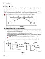
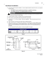
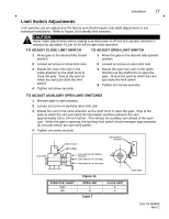
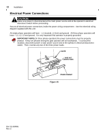
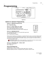
Installation 17 Limit Switch Adjustments Limit switches are pre-adjusted at the factory and should require only slight adjustments to suit individual installations. Refer to Figure 14 to identify limit switches. CAUTION Never make adjustments before making sure that power is off and that operator direction is selected by dip switch #1, pin #2 for left or right hand operation. TO ADJUST CLOSE LIMIT SWITCH TO ADJUST OPEN LIMIT SWITCH 1 Move gate to the desired fully closed position. 1 Move the gate to the desired fully opened position. 2 Loosed set screw on close limit cam. 2 Loosed set screw on open limit cam. 3 Rotate the close limit cam in the same direction as the shaft turns to close the gate. Stop at the point at which the cam just clicks the limit switch. 4 Tighten set screw securely. 3 Rotate the open limit cam in the dame direction as the shaft turns to open the gate. Stop at the point at which the cam just clicks the limit switch. 4 Tighten set screws securely. TO ADJUST AUXILIARY OPEN LIMIT SWITCHES 1 Maintain gate in open position. 2 Loosen set screw on auxiliary open limit cam. 3 Rotate the cam in the same direction as the shaft turns to open the gate. Stop at the point at which the cam just clicks the limit switch and then advance the cam approximately 1/8 to 1/4 inch further. This will put the auxiliary cam ahead of the open cam. When the gate is opening, the auxiliary limit switch should energize approximately (2) seconds before the open limit switch. 4 Tighten set screw securely. 0 1 -G 0 6 6 5F9 DRIVE SHAFT SET SCREW LIMIT SWITCH (23-2016) AUX OPEN AUX. SWITCH (OPTIONAL) (23-2017) LIMIT SWITCH "A" (23-2016) LIMIT SWITCH "B" (23-2016) OPERATOR "HAND" Right Left Figure 14 OPEN LIMIT A B Table 7 LIMIT CAM CLOSE LIMIT B A Doc 01-G0665 Rev C
-
 1
1 -
2
-
3
-
4
-
5
-
6
-
7
-
8
-
9
-
10
-
11
-
 12
12 -
 13
13 -
 14
14 -
 15
15 -
 16
16 -
 17
17 -
 18
18 -
 19
19 -
 20
20 -
 21
21 -
 22
22 -
23
-
24
-
25
-
26
-
27
-
28
-
29
-
30
-
31
 |
 |