LiftMaster SW470 SW490 S3 BOARD Manual - Page 13
Pad Mount Installation, Caution
 |
View all LiftMaster SW470 manuals
Add to My Manuals
Save this manual to your list of manuals |
Page 13 highlights
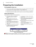
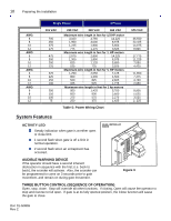
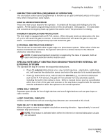
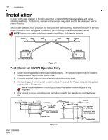
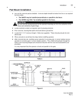
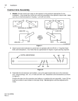
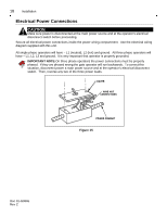
Installation 13 Pad Mount Installation 1 Lay out the concrete pad as detailed. Concrete depth should be below frost line or as required by local codes. " The SW470 may be installed perpendicular or parallel to the fence. " The SW490 may ONLY be installed parallel to the fence. CAUTION Be sure that the measurements for the operator mounting are from the centerline of the fence and centerline of gate hinge. 2 Locate electrical conduit, as required, prior to pouring concrete. 3 Pour concrete, insuring that pad is level and above ground line. 4 Locate (4) ½" X 6" minimum length L-Bolts (not supplied). These should protrude (1) inch above pad. 5 Allow concrete to set at least two days before installing operator. 6 After concrete has set, carefully secure operator to concrete pad, in correct relative secure operator to concrete pad, in correct relative position. The L-Bolts will protrude through the holes in the mounting flanges and should be secured with hex nuts and lockwashers (not provided). It is very important that the operator is level and parallel to the gate. DIMENSION TABLE A B C D SW470 9-3/4" 22-1/2" 24" 8" SW490 16" 28" 32" 8" Table 6 Figure 6 0 1 -G 0 66 5 F2 Doc 01-G0665 Rev C
-
 1
1 -
2
-
3
-
4
-
5
-
6
-
7
-
 8
8 -
 9
9 -
 10
10 -
 11
11 -
 12
12 -
 13
13 -
 14
14 -
 15
15 -
 16
16 -
 17
17 -
 18
18 -
19
-
20
-
21
-
22
-
23
-
24
-
25
-
26
-
27
-
28
-
29
-
30
-
31
 |
 |