Linksys SR2016 Cisco SR2016 and SR2024C 16-Port and 24-Port 10/100/1000 Gigabi - Page 1
Linksys SR2016 - Cisco - 10/100/1000 Gigabit Switch Manual
 |
UPC - 745883556496
View all Linksys SR2016 manuals
Add to My Manuals
Save this manual to your list of manuals |
Page 1 highlights
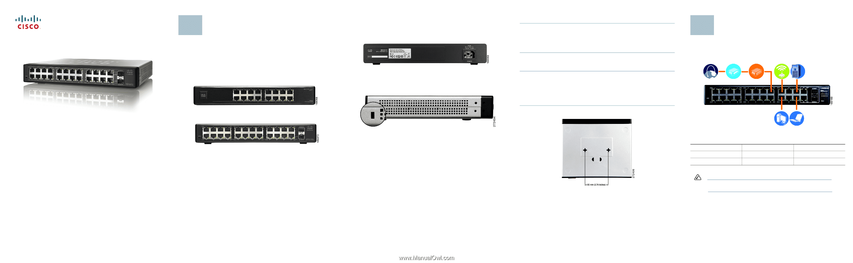
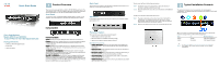
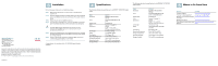
Quick Start Guide Cisco Small Business Models SR2016 and SR2024C 16 and 24-Port 10/100/1000 Gigabit Switches Package Contents • SR2016 or SR2024C Gigabit Switch • Power Cord • Quick Start Guide 1 Product Overview Thank you for choosing the 16-Port or 24-Port 10/100/1000 Gigabit Switch. The 16-Port and 24-Port 10/100/1000 Gigabit Switches provide non-blocking, wirespeed switching for your 10, 100, and 1000 megabit network clients. Front Panel The 16-and 24-Port 10/100/1000 Gigabit Switches differ in number of LEDs and ports. The LEDs and ports are located on the front panel of the Switch. Back Panel The power port is located on the back panel of the Switch.The power port is where you connect the included power cord. Side Panel Located on the side panel, the security slot is where you can attach a lock to guard against theft. Front Panel of the SR2016 Front Panel of the SR2024C System-(Green) The System LED lights when the Switch is powered on. Link/Act-(Green) Each LED lights when there is a connection made through the corresponding port. The LED also flashes when there is activity on the corresponding port. Gigabit-(Amber) Each LED lights when there is a Gigabit connection made through the corresponding port. The LED flashes when there is activity on the corresponding port. 1-16 (SR2016) or 1-24 (SR2024C)-The Ethernet ports connect to network devices, such as PCs or additional switches. All ports are auto-negotiating and have automatic MIDI/MIDI-X crossover detection. Mini-GBIC 1-2 (SR2024C)-The SR2024C Switch is equipped with two miniGBIC ports. These ports provide links to high-speed network segments or individual workstations at speeds of up to 1000Mbps (Gigabit Ethernet). These ports are shared. If you use the mini-GBIC1 port, you cannot use port 12. If you use the mini-GBIC2 port, you cannot use port 24. Placement Options There are three ways to physically install the Switch: • Set the Switch on its four rubber feet • Mount the Switch in a standard-sized rack (1U high) • Wall-mount the Switch using the wall-mount slots Rack Mount Instruction Tips • Ambient Temperature-To prevent the switch from overheating, do not operate the switch in an area that exceeds the recommended ambient temperature. • Reduced Air Flow-If you install the switch in a rack, be sure that there is adequate air flow as required. • Mechanical Loading-Be sure that the switch is level and stable when you mount the switch in a rack to avoid any hazardous condition. • Circuit Overloading-Do not overload the power outlet or circuit when installing multiple devices in a rack. • Reliable Grounding-Be sure that the switch is grounded and use suitable electrical supply connections. To rack mount the Switch, follow these instructions: STEP 1 The Switch has four mounting holes on each side. Screw an included mounting bracket into each side. STEP 2 Place the Switch in the rack, and secure the brackets with additional screws. To wall-mount the Switch, follow these instructions: STEP 1 The wall-mount slots are two crisscross slots on the Switch's bottom panel. The distance between the two slots is 95 mm (3.74 inches). Attach two screws to the wall, so that the Switch's wall-mount slots line up with the two screws. STEP 2 Maneuver the Switch so the screws are inserted into the two slots. 2 Typical Installation Scenario The application diagram shown is an example of a typical network configuration. This diagram shows the front panel of the SR2024C and is used only as a reference. When you connect your network devices, make sure you don't exceed the maximum cabling distances, listed in the following table. From Switch Switch To Switch Computer Maximum Distance 100 meters (328 feet) 100 meters (328 feet) NOTE Use Category 5e Ethernet network cables for your Gigabit connections.
-
 1
1 -
 2
2
 |
 |