MSI 651M-V User Guide - Page 27
Front Panel Connectors: JFP1 & JFP2, Chassis Intrusion Switch Connector: JCI1
 |
UPC - 816909005455
View all MSI 651M-V manuals
Add to My Manuals
Save this manual to your list of manuals |
Page 27 highlights
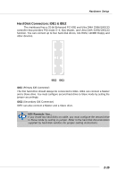
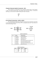
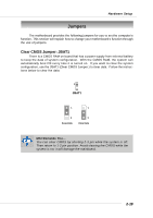
Hardware Setup Chassis Intrusion Switch Connector: JCI1 This connector is connected to 2-pin connector chassis switch. If the Chassis is open, the switch will be short. The system will record this status. To clear the warning, you must enter the BIOS setting and clear the status. JCI1 Front Panel Connectors: JFP1 & JFP2 The mainboard provides two front panel connectors for electrical connection to the front panel switches and LEDs. JFP1 is compliant with Intel® Front Panel I/O Connectivity Design Guide. JFP1 HDD LED 12 Power LED Reset Power Switch Switch 9 10 Power LED JFP2 7 8 1 2 Speaker JFP1 Pin Definition PIN SIGNAL 1 HD_LED_P 2 FP PWR/SLP 3 HD_LED_N 4 FP PWR/SLP 5 RST_SW_N 6 PWR_SW_P 7 RST_SW_P 8 PWR_SW_N 9 RSVD_DNU DESCRIPTION Hard disk LED pull-up MSG LED pull-up Hard disk active LED MSG LED pull-up Reset Switch low reference pull-down to GND Power Switch high reference pull-up Reset Switch high reference pull-up Power Switch low reference pull-down to GND Reserved. Do not use. JFP2 Pin Definition PIN SIGNAL PIN SIGNAL 1 GND 2 SPK- 3 SLED 4 BUZ+ 5 PLED 6 BUZ- 7 NC 8 SPK+ 2-17
-
 1
1 -
2
-
3
-
4
-
5
-
6
-
7
-
8
-
9
-
10
-
11
-
12
-
13
-
14
-
15
-
16
-
17
-
18
-
19
-
20
-
21
-
 22
22 -
 23
23 -
 24
24 -
 25
25 -
 26
26 -
 27
27 -
 28
28 -
 29
29 -
 30
30 -
 31
31 -
 32
32 -
33
-
34
-
35
-
36
-
37
-
38
-
39
-
40
-
41
-
42
-
43
-
44
-
45
-
46
-
47
-
48
-
49
-
50
-
51
-
52
-
53
 |
 |
