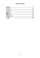
MSI 865PE NEO2-V User Guide - Page 9
Hardware Setup - memory
 |
UPC - 816909005813
View all MSI 865PE NEO2-V manuals
Add to My Manuals
Save this manual to your list of manuals |
Page 9 highlights
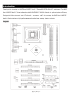
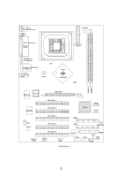
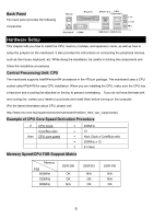
Back Panel The back panel provides the following connectors: Mo use Para llel Ke yboard COMA SPD IF-Out LA N (O pt ional ) USB Por ts US B Port s L-in L -o ut Mi c Hardware Setup This chapter tells you how to install the CPU, memory modules, and expansion cards, as well as how to setup the jumpers on the mainboard. It also provides the instructions on connecting the peripheral devices, such as the mouse, keyboard, etc. While doing the installation, be careful in holding the components and follow the installation procedures. Central Processing Unit: CPU The mainboard supports Intel®Pentium®4 processors in the 478 pin package. The mainboard uses a CPU socket called PGA478 for easy CPU installation. When you are installing the CPU, make sure the CPU has a heat sink and a cooling fan attached on the top to prevent overheating. If you do not have the heat sink and cooling fan, contact your dealer to purchase and install them before turning on the computer. (For the latest information about CPU, please visit http://www.msi.com.tw/program/products/mainboard/mbd/pro_mbd_cpu_support.php) Example of CPU Core Speed Derivation Procedure If CPU Clock Core/Bus ratio then CPU core speed = 200MHz = 12 = Host Clock x Core/Bus ratio = 200MHz x 12 = 2.4 GHz Memory Speed/CPU FSB Support Matrix Memory FSB 400MHz 533MHz 800MHz DDR 266 OK OK N/A DDR333 N/A OK OK DDR 400 N/A N/A OK 5
-
 1
1 -
2
-
3
-
 4
4 -
 5
5 -
 6
6 -
 7
7 -
 8
8 -
 9
9 -
 10
10 -
 11
11 -
 12
12 -
 13
13 -
 14
14 -
15
-
16
-
17
-
18
-
19
-
20
-
21
-
22
-
23
-
24
-
25
-
26
-
27
-
28
-
29
-
30
-
31
-
32
-
33
-
34
-
35
-
36
-
37
-
38
-
39
-
40
-
41
-
42
-
43
-
44
-
45
-
46
-
47
-
48
-
49
-
50
-
51
-
52
-
53
-
54
-
55
-
56
-
57
-
58
-
59
-
60
-
61
-
62
-
63
-
64
-
65
-
66
-
67
-
68
-
69
-
70
-
71
-
72
-
73
-
74
-
75
-
76
-
77
-
78
-
79
-
80
-
81
-
82
-
83
-
84
-
85
-
86
-
87
-
88
-
89
-
90
-
91
-
92
-
93
-
94
-
95
-
96
-
97
-
98
-
99
-
100
-
101
-
102
-
103
-
104
-
105
-
106
-
107
-
108
 |
 |
