MSI 915GVM3-V User Guide - Page 10
Hardware Setup - cpu support
 |
View all MSI 915GVM3-V manuals
Add to My Manuals
Save this manual to your list of manuals |
Page 10 highlights
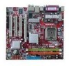
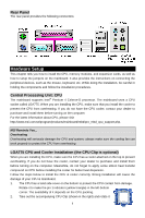
Rear Panel The rear panel provides the following connectors: Hardware Setup This chapter tells you how to install the CPU, memory modules, and expansion cards, as well as how to setup the jumpers on the mainboard. It also provides the instructions on connecting the peripheral devices, such as the mouse, keyboard, etc. While doing the installation, be careful in holding the components and follow the installation procedures. Central Processing Unit: CPU The mainboard supports Intel® Pentium 4 Celeron-D processor. The mainboard uses a CPU socket called LGA775. When you are installing the CPU, make sure that you install the cooler to prevent the CPU from overheating. If you do not have the CPU cooler, contact your dealer to purchase and install them before turning on the computer. For the latest information about CPU, please visit http://www.msi.com.tw/program/products/mainboard/mbd/pro_mbd_cpu_support.php. MSI Reminds You... Overheating Overheating will seriously damage the CPU and system; always make sure the cooling fan can work properly to protect the CPU from overheating. LGA775 CPU and Cooler Installation (the CPU Clip is optional) When you are installing the CPU, make sure the CPU has a cooler attached on the top to prevent overheating. If you do not have the cooler, contact your dealer to purchase and install them before turning on the computer. Meanwhile, do not forget to apply some silicon heat transfer compound on CPU before installing the cooler for better heat dispersion. Follow the steps below to install the CPU & cooler correctly. Wrong installation will cause the damage of your CPU & mainboard. 1. The CPU has a land side cover on the bottom to protect the CPU contact from damage. Rotate it to make the pin 1 indicator (yellow triangle) in the left-bottom corner. The availability of it depends on the CPU packing. 2. Take out the accompanying CPU Clip (shown in the right) and rotate it 4
-
 1
1 -
2
-
3
-
4
-
 5
5 -
 6
6 -
 7
7 -
 8
8 -
 9
9 -
 10
10 -
 11
11 -
 12
12 -
 13
13 -
 14
14 -
 15
15 -
16
-
17
-
18
-
19
-
20
-
21
-
22
-
23
-
24
-
25
-
26
-
27
-
28
-
29
-
30
-
31
-
32
-
33
-
34
-
35
-
36
-
37
-
38
-
39
-
40
-
41
-
42
-
43
-
44
-
45
-
46
-
47
-
48
-
49
-
50
-
51
-
52
-
53
-
54
-
55
-
56
-
57
-
58
-
59
-
60
-
61
-
62
-
63
-
64
-
65
-
66
 |
 |
