MSI 915GVM3-V User Guide - Page 11
Memory - bios update
 |
View all MSI 915GVM3-V manuals
Add to My Manuals
Save this manual to your list of manuals |
Page 11 highlights
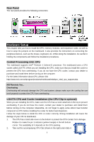
for the same direction as the CPU (Pin 1 indicator is in the left-bottom corner). 3. Use 2 hands to remove the land side cover (if any). Please note not to touch the pins. 4. Align the two pin 1 indicators (the triangles on the CPU & the CPU Clip), and use the CPU Clip to clip the CPU up, pressing the clips on both sides to the center, as the arrows shown. 5. The CPU socket has a plastic cap on it to protect the contact from damage. Before you have installed the CPU, always cover it to protect the socket pin. 6. Remove the cap from lever hinge side. The pins of socket reveal. 7. Lift the load lever up and open the load plate. 8. Correctly align the triangle of CPU Clip with the CPU chamfer, and the square on the CPU Clip to the hook of the socket. 9. Use your thumb and the middle fingers to push the clips to release the CPU, then press down the CPU with your index finger to allow the whole module to be installed onto the CPU socket. 10. The CPU is installed well on the CPU socket. 11. Visually inspect if the CPU is seated well into the socket, then remove the CPU Clip with 2 fingers. Then cover the load plate onto the package. 12. Press down the load lever lightly onto the load plate, and then secure the lever with the hook under retention tab. 13. Align the holes on the mainboard with the cooler. Push down the cooler until its four clips get wedged into the holes of the mainboard. 14. Press the four hooks down to fasten the cooler. Then rotate the locking switch (refer to the correct direction marked on it) to lock the hooks. 15. Turn over the mainboard to confirm that the clip-ends are correctly inserted. Note: If you want to uninstall the CPU, align the 4 points (see Point 8 for details) again and push the clip to lift up the CPU. MSI Reminds You... 1. Confirm if your CPU cooler is firmly installed before turning on your system. 2. Check the information in PC Health Status of H/W Monitor in BIOS for the CPU temperature. 3. Do not touch the CPU socket pins to avoid damaging. 4. Whenever CPU is not installed, always protect your CPU socket pin with the plastic cap covered to avoid damaging. 5. Please note that the mating/unmating durability of the CPU is 20 cycles. Therefore we suggest you do not plug/unplug the CPU too often. Memory The mainboard provides two 240-pin unbuffered DDR II 533/400 DIMMs. It supports the memory size up to 2GB. To operate properly, at least one DIMM module must be installed. (For the updated supporting memory modules, please visit http://www.msi.com.tw/program/products/mainboard/mbd/pro_mbd_trp_list.php) 5
-
 1
1 -
2
-
3
-
4
-
5
-
 6
6 -
 7
7 -
 8
8 -
 9
9 -
 10
10 -
 11
11 -
 12
12 -
 13
13 -
 14
14 -
 15
15 -
 16
16 -
17
-
18
-
19
-
20
-
21
-
22
-
23
-
24
-
25
-
26
-
27
-
28
-
29
-
30
-
31
-
32
-
33
-
34
-
35
-
36
-
37
-
38
-
39
-
40
-
41
-
42
-
43
-
44
-
45
-
46
-
47
-
48
-
49
-
50
-
51
-
52
-
53
-
54
-
55
-
56
-
57
-
58
-
59
-
60
-
61
-
62
-
63
-
64
-
65
-
66
 |
 |
