MSI E7505 User Guide
MSI E7505 Manual
 |
View all MSI E7505 manuals
Add to My Manuals
Save this manual to your list of manuals |
MSI E7505 manual content summary:
- MSI E7505 | User Guide - Page 1
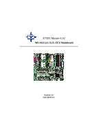
E7505 Master-LS2 MS-9121 (v1.X) E-ATX Mainboard Version 1.0 G52-S9121X1 i - MSI E7505 | User Guide - Page 2
frequency energy and, if not installed and used in accordance with the instruction manual, may cause harmful interference to radio communications. Operation of this equipment AVANT DE RACCORDER AU RESEAU. Micro-Star International MS-9121 Tested to comply with FCC Standard For Home or Office Use ii - MSI E7505 | User Guide - Page 3
If a problem arises with your system and no solution can be obtained from the user's manual, please contact your place of purchase or local distributor. Alternatively, please try the following help resources for further guidance. Visit the MSI website for FAQ, technical guide, BIOS updates, driver - MSI E7505 | User Guide - Page 4
1. Always read the safety instructions carefully. 2. Keep this User's Manual for future reference. 3. Keep this equipment away shock. 11. If any of the following situations arises, get the equipment checked by a service personnel: z The power cord or plug is damaged. z Liquid has penetrated into the - MSI E7505 | User Guide - Page 5
Support iii Safety Instructions iv Chapter 1. Getting Started 1-1 Mainboard Specifications 1-2 Mainboard Layout 1-5 MSI Special Features 1-6 PC Alert™ III 1-6 Live BIOS™/Live Driver 1-6 Live Monitor 1-8 Chapter 2. Hardware Setup 2-1 Quick Components Guide 2-2 Central Processing Unit: CPU - MSI E7505 | User Guide - Page 6
Audio Port Connectors 2-11 Parallel Port Connector: LPT1 2-12 RJ-45 LAN Jack: Giga-bit LAN 2-13 Connectors 2-14 Floppy Disk Drive Connector: FDD1 2-14 Chassis Intrusion Switch Connector: JCI1 2-14 Hard Disk Connectors: IDE1/2 2-15 Fan Power Connectors: CPUFAN1/2, SYSFAN1/2/3/4/5 2-16 Front - MSI E7505 | User Guide - Page 7
Setup 3-19 PNP/PCI Configurations 3-22 PC Health Status 3-24 Frequency/Voltage Control 3-25 Load Fail-Safe/Optimized Defaults 3-26 Set Supervisor/User Password 3-27 Troubleshooting T-1 Glossary ...G-1 vii - MSI E7505 | User Guide - Page 8
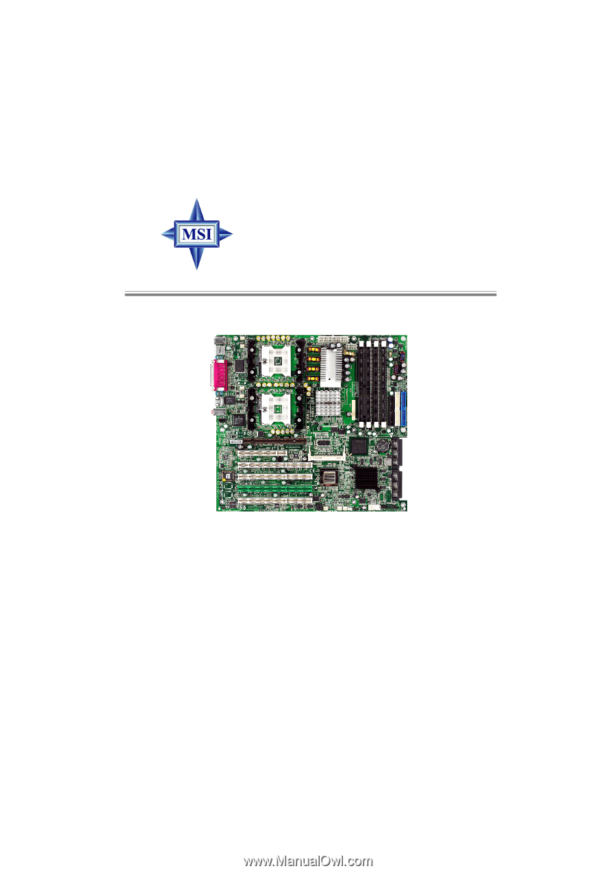
Getting Started Chapter 1. Getting Started Getting Started Thank you for purchasing the E7505 Master-LS2 (MS-9121 v1.X) E-ATX mainboard. The E7505 Master-LS2 is a superior computer mainboard based on Intel® E7505 & ICH4 chipsets for optimal system efficiency. Designed to fit the advanced Intel® Xeon - MSI E7505 | User Guide - Page 9
MS-9121 E-ATX Mainboard Mainboard Specifications CPU h Supports single/dual Intel® Xeon™ processors with 512K L2 cache. h Supports 1.8GHz ~ 2.8GHz and up. Chipset h Intel® E7505 North Bridge - Supports 100MHz/133MHz system clock. - Intel® NetBurst micro-architecture supports 400MHz/533MHz system bus - MSI E7505 | User Guide - Page 10
on the ICH4 chipset provides IDE HDD/CD-ROM with PIO, Bus Master and Ultra DMA100/66/33 operation modes. h Can connect up to four IDE devices. On-Board Peripherals h On-Board Peripherals include: - 1 x floppy port supports 2 FDDs with 360K, 720K, 1.2M, 1.44M and 2.88Mbytes - 2 x serial ports (COM - MSI E7505 | User Guide - Page 11
MS-9121 E-ATX Mainboard BIOS h The mainboard BIOS provides "Plug & Play" BIOS which detects the pe- ripheral devices and expansion cards of the board automatically. h The mainboard provides a Desktop Management Interface (DMI) function which records your mainboard specifications. Dimension h - MSI E7505 | User Guide - Page 12
DCO M BC M57 03 CKHB AGP Pro Slot Codec J14 BIOS PCI 1 PCIX1 PCIX2 PCIX3 PCIX4 J17 mPGA604 Intel E7505 PCI 2 P64H2 ICH4 J12 JBAT1 JCI1 BATT + LSI53C1030 S Y S FA N 5 S Y S FA N 3 J16 SYSFAN4 JWL1 J18 JUSB3 JFP2 JFP3 E7505 Master-LS2 (MS-9121 v1.X) E-ATX Mainboard SCSI 1 SCSI 2 1-5 - MSI E7505 | User Guide - Page 13
MS-9121 E-ATX Mainboard MSI Special Features PC Alert™ III The PC AlertTM III is a utility you can find in the CD-ROM disk. The utility is just like your PC doctor that can detect the following PC hardware status during real time operation: Ø monitor CPU & system temperatures Ø monitor fan speed(s) - MSI E7505 | User Guide - Page 14
the VGA driver online. z Live Utility - Updates the utilities online. If the product you purchased does not support any of the functions listed above, a "sorry" message is displayed. For more information on the update instructions, insert the companion CD and refer to the "Live Update Guide" under - MSI E7505 | User Guide - Page 15
MS-9121 E-ATX Mainboard Live Monitor™ The Live Monitor™ is a tool used to schedule the search for the latest BIOS/drivers version on the MSI Web site. To use the function, you need to install the "MSI Live Update 2" application. After installation, the "MSI Live Monitor" icon (as shown on the right) - MSI E7505 | User Guide - Page 16
Hardware Setup Chapter 2. Hardware Setup Hardware Setup This chapter provides you with the information about hardware setup procedures. While doing the installation, be careful in holding the components and follow the installation procedures. For some components, if you install in the wrong - MSI E7505 | User Guide - Page 17
MS-9121 E-ATX Mainboard Quick Components Guide CPUFAN1 SYSFAN1, p.2-16 CPU, p.2-3 POWER1, p.2-8 POWER2, p.2-8 DIMM1~4, p.2-6 Back Panel I/O, p.2-9 CPUFAN2 SYSFAN2, p.2-16 JCD1, p.2-19 AGP Pro, p.2-25 J14, p.2-23 PCI Slots, p.2-25 FDD1, p.2-14 IDE1/2, p.2-15 JCI1, p.2-14 JBAT1, p.2- - MSI E7505 | User Guide - Page 18
Unit: CPU The mainboard supports Single/Dual Intel® Xeon™ processors and uses two CPU sockets called Socket 604 for easy CPU installation. You can install SINGLE or DUAL CPUs on the board to meet your own needs. Keep the following points in mind before installing CPU(s): 1. If SINGLE CPU is - MSI E7505 | User Guide - Page 19
MS-9121 E-ATX Mainboard CPU Installation Procedures 1. Please turn off the power and unplug the power cord before installing the CPU. 2. Pull the lever sideways away from the socket. Make sure to raise the lever up to a 90-degree angle. 3. Look for the gold arrow. The - MSI E7505 | User Guide - Page 20
Clock x Core/Bus ratio 100MHz x 14 1.4 GHz MSI Reminds You... Overheating Overheating will seriously damage the CPU and system, always make sure the cooling fan can work properly to protect the CPU from overheating. Replacing the CPU While replacing the CPU, always turn off the ATX power supply or - MSI E7505 | User Guide - Page 21
MS-9121 E-ATX Mainboard Memory The mainboard provides 4 slots for 184-pin DDR DIMM (Double InLine Memory Module) modules and supports DDR DIMM Slots (DIMM 1~4) Memory Speed/CPU FSB Support Matrix DDR200 400MHz FSB Yes 533MHz FSB on the slots. Each DIMM slot supports up to a maximum size of 2GB - MSI E7505 | User Guide - Page 22
128MB~2GB DIMM2 128MB~2GB 128MB~2GB DIMM3 128MB~2GB 128MB~2GB DIMM4 128MB~2GB 128MB~2GB System Density 256MB~4GB 256MB~4GB 512MB~8GB MSI Reminds You... Make sure that you install memory modules of the same type and density on DDR DIMMs "in pairs" -- {DIMM1 & DIMM2} {DIMM3 & DIMM4}. Installing - MSI E7505 | User Guide - Page 23
MS-9121 E-ATX Mainboard Power Supply The mainboard supports SSI power supply for the power firmly into the connector. SSI 8-Pin Power Connector: POWER2 This connector provides 12V power output to the CPU. 24 13 12 POWER1 1 8 5 4 1 POWER2 POWER1 Pin Definition PIN SIGNAL PIN SIGNAL 1 - MSI E7505 | User Guide - Page 24
Hardware Setup Back Panel The back panel provides the following connectors: Mouse Parallel Keyboard USB COM A COM B LAN MIC L-In L-Out Mouse Connector The mainboard provides a standard PS/2® mouse mini DIN connector for attaching a PS/2® mouse. You can plug a PS/2® mouse directly into this - MSI E7505 | User Guide - Page 25
MS-9121 E-ATX Mainboard Keyboard Connector The mainboard provides a standard PS/2® keyboard mini DIN connector for attaching a PS/2® keyboard. You can plug a PS/2® keyboard directly into this - MSI E7505 | User Guide - Page 26
Hardware Setup Serial Port Connector: COM A & COM B The mainboard offers two 9-pin male DIN connectors as serial port COM A and COM B. The ports are 16550A high speed communication ports that send/receive 16 bytes FIFOs. You can attach a serial mouse or other serial devices directly to them. 1 2 3 - MSI E7505 | User Guide - Page 27
MS-9121 E-ATX Mainboard Parallel Port Connector: LPT1 The mainboard provides a 25-pin female centronic connector as LPT. A parallel port is a standard printer port that supports Enhanced Parallel Port (EPP) and Extended Capabilities Parallel Port (ECP) mode. 13 1 25 14 Pin Definition PIN - MSI E7505 | User Guide - Page 28
Hardware Setup RJ-45 LAN Jack: Giga-bit LAN The mainboard provides one standard RJ-45 jack for connection to Local Area Network (LAN). Giga-bit LAN enables data to be transferred at 1000, 100 or 10Mbps. Pin assignments vary depending on the transfer rates: 10/100Mbps or 1000Mbps. Note that Pin 1/2, - MSI E7505 | User Guide - Page 29
MS-9121 E-ATX Mainboard Connectors The mainboard provides connectors to connect to FDD, IDE HDD, case, modem, LAN, USB Ports, IR module and CPU/System/Power Supply FAN. Floppy Disk Drive Connector: FDD1 The mainboard provides a standard floppy disk drive connector that supports 360K, 720K, 1.2M, 1. - MSI E7505 | User Guide - Page 30
controller that provides PIO mode 0~4, Bus Master, and Ultra DMA 33/ 66/100 function. BIOS) and other devices. These connectors support the provided IDE hard disk cable. IDE1. IDE1 can connect a Master and a Slave drive. You can also connect a Master and a Slave drive. MSI Reminds You... If you - MSI E7505 | User Guide - Page 31
MS-9121 E-ATX Mainboard Fan Power Connectors: CPUFAN1/2, SYSFAN1/2/3/4/5 The CPUFAN1/2 (processor fans) and SYSFAN1/2/3/4/5 (system fans) support system cooling fan with +12V. It supports chipset on-board, you must use a specially designed fan with speed sensor to take advantage of the CPU fan - MSI E7505 | User Guide - Page 32
connectors for electrical connection to the front panel switches and LEDs. The JFP2 is compliant with Intel® Front Panel I/O Connectivity Design Guide. Power Power LED Switch JFP2 2 1 10 9 Speaker HDD Reset LED Switch JFP3 2 1 8 7 Power LED JFP3 Pin Definition PIN SIGNAL 1 GND 3 SLED - MSI E7505 | User Guide - Page 33
MS-9121 E-ATX Mainboard SCSI LED Connector: J18 Connect the J18 to the LED connector on the add-on SCSI adaptor and the HDD LED will blink - MSI E7505 | User Guide - Page 34
to a LAN card with Wake On LAN function. You can wake up the computer via remote control through a local area network. GND 5VSB MP_WAKEUP 1 JWL1 MSI Reminds You... To be able to use this function, you need a power supply that provides enough power for this feature. (750 mA 5V Stand-by - MSI E7505 | User Guide - Page 35
MS-9121 E-ATX Mainboard Ultra320 SCSI Connectors: SCSI 1/2 SCSI (Small Computer System Interface) is a hardware interface that allows for connection of up to 15 peripheral devices. The - MSI E7505 | User Guide - Page 36
of jumpers. Clear CMOS Jumper: JBAT1 There is a CMOS RAM on board that has a power supply from external battery to keep the data of Jumper ) to clear data. Follow the instructions below to clear the data: JBAT1 1 1 3 Keep Data 1 3 Clear Data MSI Reminds You... You can clear CMOS by shorting - MSI E7505 | User Guide - Page 37
MS-9121 E-ATX Mainboard System Configure Jumper: J12 The J12 jumper determines which mode the system will enter while powered on. During Normal Mode, the system will - MSI E7505 | User Guide - Page 38
Hardware Setup BIOS Flash Jumper: J14 This jumper is used to protect the BIOS boot block from virus infection. When locked, the BIOS boot block cannot be accessed, making BIOS update impossible. When BIOS update is intended, short pin 2 & 3 to disable BIOS flash protection. J14 1 1 3 1 3 BIOS - MSI E7505 | User Guide - Page 39
MS-9121 E-ATX Mainboard ASR Enable/Disable Jumper: J17 This jumper is used to enable/disable the ASR (Auto Server Reboot) function. J17 Disable ASR Enable ASR 2-24 - MSI E7505 | User Guide - Page 40
Hardware Setup Slots The motherboard provides one AGP Pro slot, one 32-bit Master PCI slot, one Mini PCI slot, and four 64-bit PCI-X slots. AGP Pro Slot 32-bit PCI Slot 64-bit PCI-X Slots Mini PCI - MSI E7505 | User Guide - Page 41
MS-9121 E-ATX Mainboard Mini PCI bus: This bus is used to connect the MS-9513 VGA card or MS-9514 IEEE 1394 card. MS-9513 VGA card Installing the card: 1. Locate the Mini PCI slot on the mainboard. MS-9514 IEEE 1394 card Mini PCI slot 2. Place the card over the Mini PCI slot and gently - MSI E7505 | User Guide - Page 42
end and the other on the left end). Align the two fixing holes on the card with the supporters and press the card carefully down until the fixing holes get locked by the supporters. 4. Push the retaining clips (on two ends of the slot) inwards until they lock onto the notches in - MSI E7505 | User Guide - Page 43
MS-9121 E-ATX Mainboard 2. Clip the other supporter and press it downwards until it withdraws from the fixing hole. 3. The card will automatically bound upwards after being released from the supporters. 4. Remove the card from the Mini PCI slot. supporter 2-28 - MSI E7505 | User Guide - Page 44
Slot 1 PCI Slot 2 (Mini PCI) P64H2 LSI53C1030 PCI-X Slot 3 (SCSI RAID) PCI-X Slot 4 GIGABIT LAN PCI-X Slot 1 PCI-X Slot 2 MS-9513 (VGA Card) MS-9514 (1394 Card) INT A# PIRQA_L PIRQF_L PIRQG_L PIRQC_L PAIRQ8 PAIRQ0 PAIRQ4 PBIRQ0 PBIRQ4 PBIRQ8 PIRQG_L PIRQG_L INT B# PIRQB_L PIRQG_L N/A N/A PAIRQ9 - MSI E7505 | User Guide - Page 45
BIOS Setup Chapter 3. BIOS Setup BIOS Setup This chapter provides information on the BIOS Setup program and allows you to configure the system for optimum use. You may need to run the Setup program when: ” An error message appears on the screen during the system booting up, and requests you to run - MSI E7505 | User Guide - Page 46
MS-9121 E-ATX Mainboard Entering Setup Power on the computer and the system will start POST (Power On Self Test) process. When the message below appears on - MSI E7505 | User Guide - Page 47
screen lists the appropriate keys to use and the possible selections for the highlighted item. Press to exit the Help screen. MSI Reminds You... The items under each BIOS category described in this chapter are under continuous update for better system performance. Therefore, the description - MSI E7505 | User Guide - Page 48
MS-9121 E-ATX Mainboard The Main Menu Once you enter Award Workstation BIOS CMOS Setup Utility, the Main Menu will appear on the screen. The Main Menu - MSI E7505 | User Guide - Page 49
BIOS Setup PNP/PCI Configurations This entry appears if your system supports PnP/PCI. PC Health Status This entry shows your PC health status. Frequency/Voltage Control Use this menu to specify your settings for frequency/voltage - MSI E7505 | User Guide - Page 50
MS-9121 E-ATX Mainboard Standard CMOS Features The items inside Standard CMOS current time). The time format is . IDE Primary/Secondary Master/Slave Press PgUp/ or PgDn/ to select Manual, None, Auto type. Note that the specifications of your drive must match with the - MSI E7505 | User Guide - Page 51
improper information for this category. If your hard disk drive type is not matched or listed, you can use Manual to define your own drive type manually. If you select Manual, related information is asked to be entered to the following items. Enter the information directly from the keyboard. This - MSI E7505 | User Guide - Page 52
MS-9121 E-ATX Mainboard Advanced BIOS Features Virus Warning The item is to set 1 cache) and external cache (also known as L2 or level 2 cache). Setting options: Disabled, Enabled. CPU L3 Cache Level 3 cache is the extra cache built into motherboards between the microprocessor and the main memory. - MSI E7505 | User Guide - Page 53
: Enabled, Disabled. MSI Reminds You... Enabling the functionality of Hyper-Threading Technology for your computer system requires ALL of the following platform Components: *CPU: Intel® Pentium® 4 or Xeon™ Processors with HT Technology; *Chipset: Intel® Chipsets that support HT Technology; *BIOS - MSI E7505 | User Guide - Page 54
MS-9121 E-ATX Mainboard Boot Other Device Setting the option to Enabled allows the system to try to boot from other devices if the system fails to - MSI E7505 | User Guide - Page 55
allows you to select which MPS (Multi-Processor Specification) version to be used for the operating system. You need to select the MPS version supported by your operating system. To find out which version to use, consult the vendor of your operating system. Settings: 1.4, 1.1. OS Select For DRAM - MSI E7505 | User Guide - Page 56
MS-9121 E-ATX Mainboard Advanced Chipset Features MSI Reminds You... Change these settings only if you are familiar with the chipset. DRAM Timing Control Press to enter the sub-menu and the - MSI E7505 | User Guide - Page 57
Selecting By SPD makes the following settings automatically determined by BIOS according to the configurations on the SPD. Setting options: By SPD, Manual. CAS Latency Time This setting controls the timing delay (in clock cycles) before SDRAM starts a read command after receiving it. Setting options - MSI E7505 | User Guide - Page 58
MS-9121 E- support compliance with PCI specification version 2.1. Setting options: Enabled, Disabled. Delay Prior to Thermal When the CPU This setting allows you to manually set the AGP mode of your system. The setting you choose depends on what mode your video card supports. Setting options: 2X Mode - MSI E7505 | User Guide - Page 59
the sub-menu and the following screen appears: Onboard FDC Controller Select Enabled if your system has a floppy disk controller (FDD) installed on the system board and you wish to use it. If you install add-on FDC or the system has no floppy drive, select Disabled in this field. The - MSI E7505 | User Guide - Page 60
MS-9121 E-ATX Mainboard Port There is a built-in parallel port on the on-board Super I/O chipset that provides Standard, ECP, and EPP features. mode only. Choosing "ECP + EPP" will allow the onboard parallel port to support both the ECP and EPP modes simultaneously. ECP Mode Use DMA The ECP mode - MSI E7505 | User Guide - Page 61
. On-Chip Primary/Secondary PCI IDE The integrated peripheral controller contains an IDE interface with support for two IDE channels. Choose Enabled to activate each channel separately. IDE Primary/Secondary Master/Slave PIO The four items allow you to set a PIO (Programmed Input/Output) mode for - MSI E7505 | User Guide - Page 62
MS-9121 E-ATX Mainboard it and your operating environment contains a DMA driver. If both your hard drive and software support Ultra DMA 33 (or higher), select Auto to enable BIOS support. Onboard Device Press to enter the sub-menu and the following screen appears: USB Controller Select - MSI E7505 | User Guide - Page 63
saving mode for ACPI function if your operating system supports ACPI, such as Windows 98SE, Windows ME and Windows 2000. The default setting: S1/POS The S1 sleep mode is a low power state. In this state, no system context is lost (CPU or chipset) and hardware maintains all system context. Power - MSI E7505 | User Guide - Page 64
MS-9121 E-ATX Mainboard Video Off Method This determines the manner in which the Grant (saves the state of the entire system to disk and then powers off the system), PwrOn Suspend (the CPU and core system remain powered on in a very low-power mode). Modem Use IRQ Name the interrupt request (IRQ - MSI E7505 | User Guide - Page 65
detected. Setting options: Enabled, Disabled. MSI Reminds You... You need to install a modem card supporting power on function for "Power On by specifies the time for Resume by Alarm. Format is . MSI Reminds You... If you have changed this setting, you must let the system boot - MSI E7505 | User Guide - Page 66
MS-9121 E-ATX Mainboard PNP/PCI Configurations This section describes configuring the PCI bus system and PnP (Plug & Play) feature. PCI, or Peripheral Component Interconnect, is a system which allows I/O devices to operate at speeds nearing the speed the CPU this field to "manual" choose specific - MSI E7505 | User Guide - Page 67
items are adjustable only when Resources Controlled By is set to Manual. Press and you will enter the sub-menu of set to Enabled, multiple VGA devices operating on different buses can handle data from the CPU on each set of palette registers on every video device. Bit 5 of the command - MSI E7505 | User Guide - Page 68
MS-9121 E-ATX Mainboard PC Health Status This section shows the status of your CPU, fan, overall system status, etc. Monitor the warning mechanism will be activated. This helps to prevent the CPU overheating problem. Shutdown Temperature This option specifies the shutdown temperature level for the - MSI E7505 | User Guide - Page 69
menu to specify your settings for frequency/voltage control. CPU Clock Ratio This setting controls the multiplier that is used of the pulses are reduced to flatter curves. If you do not have any EMI problem, leave the setting at Disabled for optimal system stability and performance. But if you are - MSI E7505 | User Guide - Page 70
MS-9121 E-ATX Mainboard Load Fail-Safe/Optimized Defaults The two options on the main menu allow users to restore all of the BIOS settings to the - MSI E7505 | User Guide - Page 71
is required both at boot and at entry to Setup. If set to Setup, password prompt only occurs when you try to enter Setup. MSI Reminds You... About Supervisor Password & User Password: Supervisor password: Can enter and change the settings of the setup menu. User password: Can only enter - MSI E7505 | User Guide - Page 72
the special tech issue, http://www.msi.com.tw/support/ techexpress/special_tech/smartled.htm Q: I used my MSI motherboard and got an error message, "Primary IDE Channel No 80 Conductor Cable Installed" while the system detected hard drives. A: This is not a problem. It merely means that you're - MSI E7505 | User Guide - Page 73
MS-9121 E-ATX Mainboard A: We strongly recommend that you do NOT connect those described CPU fan directly to your the BIOS boot recovery feature as described in http://www.msi.com.tw/support/bios/boot.htm 2. Try to clear the CMOS If problem still persists, ask your reseller for new BIOS chip - MSI E7505 | User Guide - Page 74
Troubleshooting Q: How do I update the BIOS? A: Please refer to http://www.msi.com.tw/support/bios/note.htm for details. Q: How do I identify the BIOS version? number. 6th - 7th digit refers to the customer as MS = all standard customers. V1.0 refers to the BIOS version. 091096 refers to the - MSI E7505 | User Guide - Page 75
MS-9121 E-ATX Mainboard Q: After I flashed the BIOS and rebooted the system, the screen went blank. A: For AMI BIOS Rename the desired AMI BIOS file to AMIBOOT. - MSI E7505 | User Guide - Page 76
the computer. Windows 98/98SE, Windows 2000 and Windows ME can fully support ACPI to allow users managing the system power flexibly. AGP (Accelerated Graphics a local bus that connects the internal components to the CPU and main memory. Cache A special memory subsystem that is used to speed up - MSI E7505 | User Guide - Page 77
MS-9121 E-ATX Mainboard contents of frequently accessed RAM locations and the addresses clock cycles per second. Since modern CPUs run much faster (up to 533 MHz), the CPU can execute several instructions in a single clock tick. CMOS (Complementary Metal-Oxide Semiconductor) CMOS is a widely used - MSI E7505 | User Guide - Page 78
makes flash memory faster. EIDE Short for Enhanced IDE, a newer version of the IDE mass storage device interface standard developed by Western Digital Corporation. It supports data rates of between 4 and 16.6 MBps, about three to four times faster than the old IDE standard. In addition, it can - MSI E7505 | User Guide - Page 79
MS-9121 standard, also known as FireWire or iLink, which supports data transfer rates of up to 400 Mbps for conflicts used to be a common problem when adding expansion boards, but the Plug-and-Play or an enterprise. It is made up of servers, workstations, shared resources, a network operating system - MSI E7505 | User Guide - Page 80
drivers. LPT (Line Printer Terminal) Logical device name for a line printer; a name reserved by the MS The PCI controller can exchange data with the system's CPU either 32 bits or 64 bits at a time configuring the system manually. To implement this useful feature, both the BIOS that supports PnP and - MSI E7505 | User Guide - Page 81
MS-9121 E-ATX Mainboard PS/2 Port A type of port developed by IBM for connecting a mouse or keyboard to a PC. The PS/2 port supports a mini DIN plug containing just 6 pins. Most modern PCs equipped with PS/2 ports so that the special port can be used by another device, such
-
 1
1 -
 2
2 -
 3
3 -
 4
4 -
 5
5 -
 6
6 -
 7
7 -
8
-
9
-
10
-
11
-
12
-
13
-
14
-
15
-
16
-
17
-
18
-
19
-
20
-
21
-
22
-
23
-
24
-
25
-
26
-
27
-
28
-
29
-
30
-
31
-
32
-
33
-
34
-
35
-
36
-
37
-
38
-
39
-
40
-
41
-
42
-
43
-
44
-
45
-
46
-
47
-
48
-
49
-
50
-
51
-
52
-
53
-
54
-
55
-
56
-
57
-
58
-
59
-
60
-
61
-
62
-
63
-
64
-
65
-
66
-
67
-
68
-
69
-
70
-
71
-
72
-
73
-
74
-
75
-
76
-
77
-
78
-
79
-
80
-
81
 |
 |
Version 1.0
G52-S9121X1
E7505 Master-LS2
MS-9121 (v1.X) E-ATX Mainboard