MSI G31TM-P21 User Guide - Page 16
if YOU INsTAll TwO ide DEvIcEs ON ThE sAmE cAblE, YOU mUsT cONfigUrE ThE DrIvEs - power supply
 |
UPC - 816909060331
View all MSI G31TM-P21 manuals
Add to My Manuals
Save this manual to your list of manuals |
Page 16 highlights
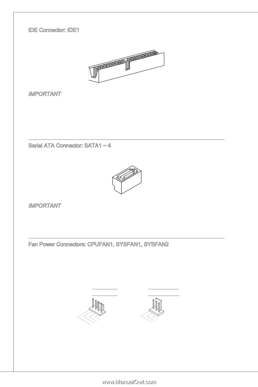
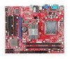
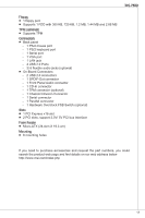
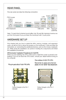
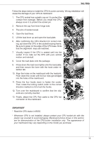
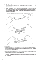
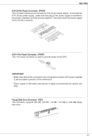
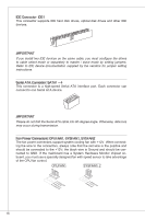
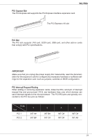
IDE Connector: IDE1 This connector supports IDE hard disk drives, optical disk drives and other IDE devices. Important If you install two IDE devices on the same cable, you must configure the drives to cable select mode or separately to master / slave mode by setting jumpers. Refer to IDE device documentation supplied by the vendors for jumper setting instructions. Serial ATA Connector: SATA1 ~ 4 This connector is a high-speed Serial ATA interface port. Each connector can connect to one Serial ATA device. Important Please do not fold the Serial ATA cable into 90-degree angle. Otherwise, data loss may occur during transmission. Fan Power Connectors: CPUFAN1, SYSFAN1, SYSFAN2 The fan power connectors support system cooling fan with +12V. When connecting the wire to the connectors, always note that the red wire is the positive and should be connected to the +12V; the black wire is Ground and should be connected to GND. If the mainboard has a System Hardware Monitor chipset onboard, you must use a specially designed fan with speed sensor to take advantage of the CPU fan control. CPUFAN1 SYSFAN1/ 2 4.3C.oS2n.e+1tnr.1osG2lorVround 3.S2.e+1n1.sG2orVround 16
-
 1
1 -
2
-
3
-
4
-
5
-
6
-
7
-
8
-
9
-
10
-
 11
11 -
 12
12 -
 13
13 -
 14
14 -
 15
15 -
 16
16 -
 17
17 -
 18
18 -
 19
19 -
 20
20 -
 21
21 -
22
-
23
-
24
-
25
-
26
-
27
-
28
-
29
-
30
-
31
-
32
-
33
-
34
-
35
-
36
-
37
-
38
-
39
-
40
-
41
-
42
-
43
-
44
-
45
-
46
-
47
-
48
-
49
-
50
-
51
-
52
-
53
-
54
-
55
-
56
-
57
-
58
-
59
-
60
-
61
-
62
-
63
-
64
-
65
-
66
-
67
-
68
-
69
-
70
-
71
-
72
-
73
-
74
-
75
-
76
-
77
-
78
-
79
-
80
-
81
-
82
-
83
-
84
-
85
-
86
-
87
-
88
-
89
-
90
-
91
-
92
-
93
-
94
-
95
-
96
-
97
-
98
-
99
-
100
-
101
-
102
-
103
-
104
-
105
-
106
-
107
-
108
-
109
-
110
-
111
-
112
-
113
-
114
-
115
-
116
-
117
-
118
-
119
-
120
-
121
-
122
-
123
-
124
-
125
-
126
-
127
-
128
-
129
-
130
-
131
-
132
-
133
-
134
-
135
-
136
-
137
-
138
-
139
-
140
-
141
-
142
-
143
-
144
-
145
-
146
-
147
-
148
-
149
-
150
-
151
-
152
-
153
 |
 |