MSI K8N NEO2 PLATINUM User Guide - Page 33
IEEE 1394 Connectors: J1394_1 / J1394_2 Optional, Front Panel Audio Connector: JAUD1, J1394_1
 |
UPC - 816909006148
View all MSI K8N NEO2 PLATINUM manuals
Add to My Manuals
Save this manual to your list of manuals |
Page 33 highlights
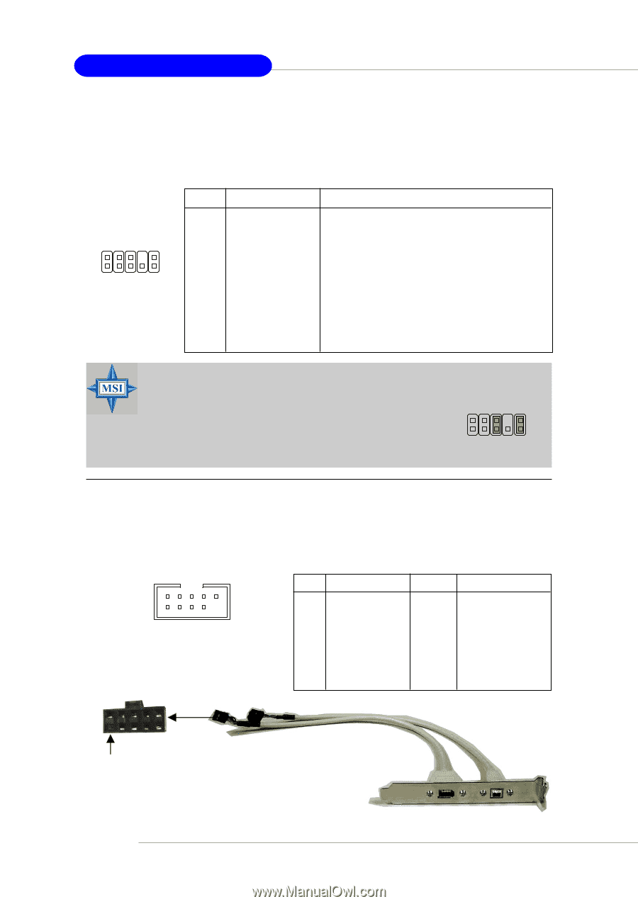
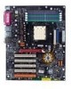
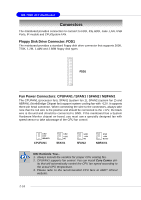
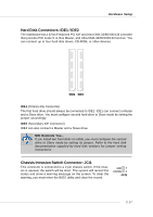
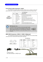
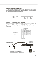
MS-7025 ATX Mainboard Front Panel Audio Connector: JAUD1 The JAUD1 front panel audio connector allows you to connect to the front panel audio and is compliant with Intel® Front Panel I/O Connectivity Design Guide. PIN SIGNAL Pin Definition DESCRIPTION 1 JAUD1 2 3 2 10 4 1 9 5 6 7 8 9 10 AUD_MIC AUD_GND AUD_MIC_BIAS AUD_VCC AUD_FPOUT_R AUD_RET_R HP_ON KEY AUD_FPOUT_L AUD_RET_L Front panel microphone input signal Ground used by analog audio circuits Microphone power Filtered +5V used by analog audio circuits Right channel audio signal to front panel Right channel audio signal return from front panel Reserved for future use to control headphone amplifier No pin Left channel audio signal to front panel Left channel audio signal return from front panel MSI Reminds You... If you don't want to connect to the front audio header, pins 5 & 6, 9 & 10 have to be jumpered in order to have signal output directed to the rear audio ports. Otherwise, the Line-Out connector on the back panel will not function. 6 10 59 IEEE 1394 Connectors: J1394_1 / J1394_2 (Optional) The mainboard provides two 1394 pin headers that allow you to connect IEEE 1394 ports via an external IEEE1394 bracket (optional). Pin Definition 2 10 1 9 J1394_1, J1394_2 PIN SIGNAL PIN 1 TPA+ 2 3 Ground 4 5 TPB+ 6 7 Cable power 8 9 Key (no pin) 10 SIGNAL TPAGround TPBCable power Ground IEEE1394 Bracket (Optional) Foolproof Design (the 1394 pinheader in GREEN color) 2-20
-
 1
1 -
2
-
3
-
4
-
5
-
6
-
7
-
8
-
9
-
10
-
11
-
12
-
13
-
14
-
15
-
16
-
17
-
18
-
19
-
20
-
21
-
22
-
23
-
24
-
25
-
26
-
27
-
 28
28 -
 29
29 -
 30
30 -
 31
31 -
 32
32 -
 33
33 -
 34
34 -
 35
35 -
 36
36 -
 37
37 -
 38
38 -
39
-
40
-
41
-
42
-
43
-
44
-
45
-
46
-
47
-
48
-
49
-
50
-
51
-
52
-
53
-
54
-
55
-
56
-
57
-
58
-
59
-
60
-
61
-
62
-
63
-
64
-
65
-
66
-
67
-
68
-
69
-
70
-
71
-
72
-
73
-
74
-
75
-
76
-
77
-
78
-
79
-
80
-
81
-
82
-
83
-
84
-
85
-
86
-
87
-
88
-
89
-
90
-
91
-
92
-
93
-
94
-
95
-
96
-
97
-
98
-
99
-
100
-
101
-
102
-
103
-
104
-
105
-
106
-
107
-
108
-
109
-
110
-
111
-
112
-
113
 |
 |