MSI K9N6SGM-V User Guide - Page 12
Memory, Power Supply, ATX 24-Pin Power Connector: JWR1, ATX 12V Power Connector: JPW1, Floppy Disk - socket
 |
UPC - 816909036312
View all MSI K9N6SGM-V manuals
Add to My Manuals
Save this manual to your list of manuals |
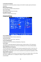
Page 12 highlights
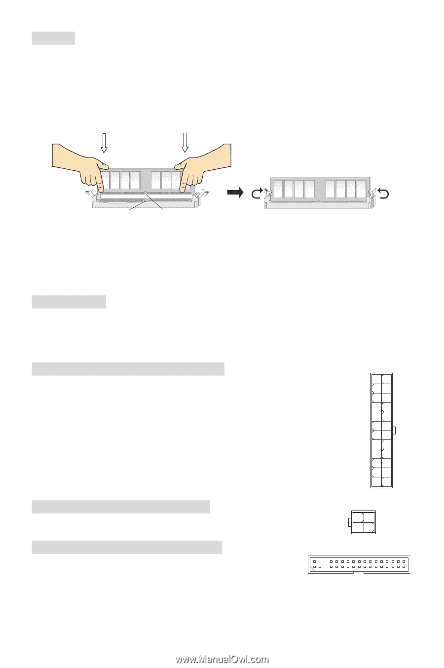
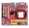
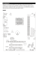
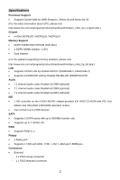
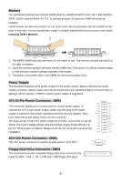
Memory The mainboard provides two 240-pin DIMM slots for unbuffered DDR II 533 / 667 / 800 SDRAM (DDR II 800 is only for Athlon 64 X2). To operate properly, at least one DIMM slot must be installed. Install at least one Memory module on one of the slots. Memory modules can be installed on the slots in any order. You can install either single- or double-sided modules to meet your own needs. Installing DDR II Modules Volt Notch 1. The DDR II DIMM has only one notch on the center of slot. The memory module will only fit in the right orientation. 2. Insert the memory module vertically into the DIMM slot. Then push it in until the golden finger on the memory module is deeply inserted in the socket. 3. The plastic clip at each side of the DIMM slot will automatically close. Power Supply The mainboard supports ATX power supply for the power system. Before inserting the power supply connector, always make sure that all components are installed properly to ensure that no damage will be caused. A 300W or above power supply is suggested. ATX 24-Pin Power Connector: JWR1 This connector allows you to connect an ATX 24-pin power supply. To connect the ATX 24-pin power supply, make sure the plug of the power supply is inserted in the proper orientation and the pins are aligned. Then push down the power supply firmly into the connector. You may use the 20-pin ATX power supply as you like. If you'd like to use the 20-pin ATX power supply, please plug your power supply along with pin 1 & pin 13. There is also a foolproof design on pin 11, 12, 23 & 24 to avoid wrong installation. +3.3V +12V +12V 5VSB PWR OK GND +5V GND +5V GND +3.3V +3.3V GND +5V +5V +5V Res GND GND GND PS-ON# GND -12V +3.3V ATX 12V Power Connector: JPW1 This 12V power connector is used to provide power to the CPU. Floppy Disk Drive Connector: FDD1 The mainboard provides a standard floppy disk drive connector that supports 360K, 720K, 1.2M, 1.44M and 2.88M floppy disk types. +12V +12V GND GND 6
-
 1
1 -
2
-
3
-
4
-
5
-
6
-
 7
7 -
 8
8 -
 9
9 -
 10
10 -
 11
11 -
 12
12 -
 13
13 -
 14
14 -
 15
15 -
 16
16 -
 17
17 -
18
-
19
-
20
-
21
-
22
-
23
-
24
-
25
-
26
-
27
-
28
-
29
-
30
-
31
-
32
-
33
-
34
-
35
-
36
-
37
-
38
-
39
-
40
-
41
-
42
-
43
-
44
-
45
-
46
-
47
-
48
-
49
-
50
-
51
-
52
-
53
-
54
-
55
-
56
-
57
-
58
-
59
-
60
-
61
-
62
-
63
-
64
-
65
-
66
-
67
-
68
-
69
-
70
-
71
-
72
-
73
-
74
-
75
-
76
-
77
-
78
-
79
-
80
-
81
-
82
-
83
-
84
-
85
-
86
-
87
-
88
-
89
-
90
-
91
-
92
-
93
-
94
 |
 |