MSI K9N6SGM-V User Guide - Page 14
Front Panel Audio Connector: JAUD1 - board
 |
UPC - 816909036312
View all MSI K9N6SGM-V manuals
Add to My Manuals
Save this manual to your list of manuals |
Page 14 highlights
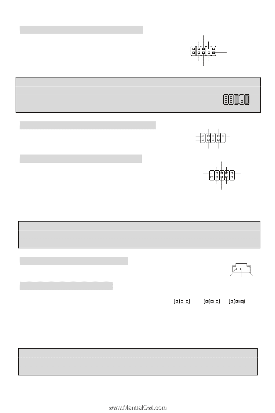
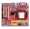
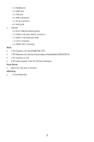
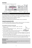
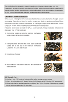
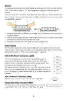
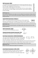
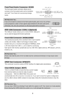
Front Panel Audio Connector: JAUD1 The front panel audio connector allows you to connect to the front panel audio and is compliant with Intel® Front Panel I/O Connectivity Design Guide. AUD_RET_R AUD_VCC Key (2)AUD_GND (1)AUD_MIC AUD_RET_L(10) AUD_FPOUT_L(9) AUD_MIC_BIAS HP_ON AUD_FPOUT_R MSI Reminds You... If you do not want to connect to the front audio header, pins 5 & 6, 9 & 10 have to be jumpered in order to have signal output directed to the rear audio ports. 2 1 10 9 Otherwise, the Line-Out connector on the back panel will not function. IEEE 1394 Connector: J1394_1 (Optional) The 1394 pin header allows you to connect IEEE 1394 ports via an external IEEE1394 bracket (optional) TPBGND Cable power (2)TPA(1)TPA+ GND(10) Key,no pin(9) Front USB Connector: JUSB1/JUSB2 The mainboard provides three standard USB 2.0 pin headers JUSB1 and JUSB2. USB2.0 technology increases data GND Cable power TPBU+SB0+ GND USB0- (9)Key (10)USB0C VCC(1) VCC(2) transfer rate up to a maximum throughput of 480Mbps, which is 40 times faster than USB 1.1, and is ideal for connecting GND USB1USB1+ high-speed USB interface peripherals such as USB HDD, digital cameras, MP3 players, printers, modems, etc. MSI Reminds You... Please note that the pins of VCC & GND must be connected correctly or it may cause some damage SPDIF-Out Connector: SPDOUT1 This connector is used to connect SPDIF interface for digital audio transmission. Clear CMOS Jumper: JBAT1 VCC SPDIF GND There is a CMOS RAM on board that has a power supply from external battery to keep the data of system configuration. With the CMOS RAM, the system can 1 23 1 23 1 23 Keep Data Clear Data automatically boot OS every time it is turned on. If you want to clear the system configuration, use the JBAT1 (Clear CMOS Jumper) to clear data. Follow the instructions below to clear the data: MSI Reminds You... You can clear CMOS by shorting 2-3 pin while the system is off. Then return to 1-2 pin position. Avoid clearing the CMOS while the system is on; it will damage the mainboard. 8
-
 1
1 -
2
-
3
-
4
-
5
-
6
-
7
-
8
-
 9
9 -
 10
10 -
 11
11 -
 12
12 -
 13
13 -
 14
14 -
 15
15 -
 16
16 -
 17
17 -
 18
18 -
 19
19 -
20
-
21
-
22
-
23
-
24
-
25
-
26
-
27
-
28
-
29
-
30
-
31
-
32
-
33
-
34
-
35
-
36
-
37
-
38
-
39
-
40
-
41
-
42
-
43
-
44
-
45
-
46
-
47
-
48
-
49
-
50
-
51
-
52
-
53
-
54
-
55
-
56
-
57
-
58
-
59
-
60
-
61
-
62
-
63
-
64
-
65
-
66
-
67
-
68
-
69
-
70
-
71
-
72
-
73
-
74
-
75
-
76
-
77
-
78
-
79
-
80
-
81
-
82
-
83
-
84
-
85
-
86
-
87
-
88
-
89
-
90
-
91
-
92
-
93
-
94
 |
 |