MSI MEG B550 UNIFY-X User Manual
MSI MEG B550 UNIFY-X Manual
 |
View all MSI MEG B550 UNIFY-X manuals
Add to My Manuals
Save this manual to your list of manuals |
MSI MEG B550 UNIFY-X manual content summary:
- MSI MEG B550 UNIFY-X | User Manual - Page 1
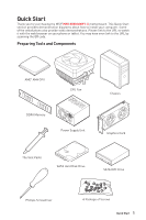
Quick Start Thank you for purchasing the MSI® MEG B550 UNIFY-X motherboard. This Quick Start section provides demonstration diagrams about how to install your computer. Some of the installations also provide video demonstrations. Please link to the - MSI MEG B550 UNIFY-X | User Manual - Page 2
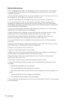
adhere to the following instructions to ensure successful motherboard checked by service personnel: ▪▪Liquid has penetrated into the computer. ▪▪The motherboard has been exposed to moisture. ▪▪The motherboard does not work well or you can not get it work according to user guide. ▪▪The motherboard - MSI MEG B550 UNIFY-X | User Manual - Page 3
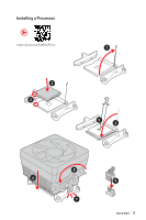
Installing a Processor ⚽ ⚽ https://youtu.be/Xv89nhFk1vc 3 2 1 5 4 8 6 9 7 Quick Start 3 - MSI MEG B550 UNIFY-X | User Manual - Page 4
⚠⚠Important If you are installing the screw-type CPU heatsink, please follow the figure below to remove the retention module first and then install the heatsink. 1 2 3 4 Quick Start - MSI MEG B550 UNIFY-X | User Manual - Page 5
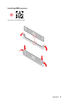
Installing DDR4 memory ⚽ ⚽ http://youtu.be/T03aDrJPyQs Quick Start 5 - MSI MEG B550 UNIFY-X | User Manual - Page 6
Connecting the Front Panel Header ⚽ ⚽ http://youtu.be/DPELIdVNZUI POPWOEWRELREHLDD-EDDL+ED RESET SW POWER SW Power LED Power Switch - -+ -- ++ JFP1 2 1 + 10 9 Reserved HDD LED Reset Switch 1 HDD LED + 2 3 HDD LED - 4 5 Reset Switch 6 7 Reset Switch 8 9 Reserved 10 Power - MSI MEG B550 UNIFY-X | User Manual - Page 7
Installing the Motherboard ⚽ ⚽ https://youtu.be/wWI6Qt51Wnc 1 Torque: 3 kgf·cm* 2 *3 kgf·cm = 0.3 N·m = 2.6 lbf·in BAT1 Quick Start 7 - MSI MEG B550 UNIFY-X | User Manual - Page 8
Connecting the Power Connectors ⚽ ⚽ http://youtu.be/gkDYyR_83I4 ATX_PWR1 CPU_PWR1 8 Quick Start CPU_PWR2 PCIE_PWR1 - MSI MEG B550 UNIFY-X | User Manual - Page 9
Installing SATA Drives http://youtu.be/RZsMpqxythc 2 1 3 5 4 Quick Start 9 - MSI MEG B550 UNIFY-X | User Manual - Page 10
Installing a Graphics Card ⚽ ⚽ http://youtu.be/mG0GZpr9w_A 1 3 2 5 10 Quick Start 4 6 - MSI MEG B550 UNIFY-X | User Manual - Page 11
Connecting Peripheral Devices Processor with integrated graphics Quick Start 11 - MSI MEG B550 UNIFY-X | User Manual - Page 12
Power On 1 2 3 4 12 Quick Start - MSI MEG B550 UNIFY-X | User Manual - Page 13
Tools and Components 1 Safety Information 2 Installing a Processor 3 Installing DDR4 memory 5 Connecting the Front Panel Header 6 Installing the Motherboard 7 Connecting the Power Connectors 8 Installing SATA Drives 9 Installing a Graphics Card 10 Connecting Peripheral Devices 11 Power On - MSI MEG B550 UNIFY-X | User Manual - Page 14
MONITOR Menu 71 AMD RAID Configuration 73 Enabling RAIDXpert2 Configuration Utility 73 Initializing Disks...74 Creating Arrays...75 Deleting Arrays...76 Installing RAID Driver 77 Troubleshooting 78 14 Contents - MSI MEG B550 UNIFY-X | User Manual - Page 15
G-Series desktop processors for AM4 socket AMD B550 Chipset ∙∙2x DDR4 memory slots, support up to 64GB* ▪▪Supports DDR4 1866/ 2133/ 2400/ 2667/ memory architecture ∙∙Supports non-ECC UDIMM memory ∙∙Supports ECC UDIMM memory (non-ECC mode) ∙∙Supports un-buffered memory * Please refer www.msi.com for - MSI MEG B550 UNIFY-X | User Manual - Page 16
PCIe 3.0 x2 ▫▫CPU support mode (From CPU) - supports PCIe 4.0/ 3.0 x4 Supports 2280 storage devices ▪▪M2_3 slot ▫▫Chipset support mode (default, from Chipset ) supports PCIe 3.0 x2** ▫▫CPU support mode (From CPU) - supports PCIe 4.0/ 3.0 x4 Supports SATA 6Gb/s* ▫▫Supports 2280/ 22110 storage - MSI MEG B550 UNIFY-X | User Manual - Page 17
Wireless LAN & Bluetooth® Audio Continued from previous page AMD Processor ∙∙1x PCIe 4.0/ 3.0 x16 slot (PCI_E1)* ▪▪Supports x16 or x8 mode** AMD B550 Chipset ∙∙1x PCIe 3.0 x16 slot , support x4 mode (PCI_E4)*** ∙∙2x PCIe 3.0 x1 slots (PCI_E2 & PCI_E3)**** * PCIe specifications may vary depending on - MSI MEG B550 UNIFY-X | User Manual - Page 18
6Gb/s connectors ∙∙4x M.2 slots (M-Key) ∙∙1x USB 3.2 Gen 2 10Gbps Type-C port ∙∙1x USB 3.2 Gen 1 5Gbps connector (supports additional 2 USB 3.2 Gen 1 5Gbps ports) ∙∙2x USB 2.0 connectors (supports additional 4 USB 2.0 ports) ∙∙1x 4-pin CPU fan connector ∙∙1x 4-pin water-pump fan connector ∙∙6x 4-pin - MSI MEG B550 UNIFY-X | User Manual - Page 19
Continued from previous page Back Panel Connectors ∙∙1x Clear CMOS Button ∙∙1x Flash BIOS Button ∙∙1x PS/2 keyboard/ mouse combo port ∙∙4x USB 2.0 Type-A ports ∙∙1x HDMI port ∙∙2x USB 3.2 Gen 2 10Gbps Type-A ports ∙∙1x 2.5 Gbps LAN (RJ45) port ∙∙1x USB 3.2 Gen 2 10Gbps Type-A port ∙∙1x USB 3.2 Gen - MSI MEG B550 UNIFY-X | User Manual - Page 20
Hardware Monitor ∙∙True Color ∙∙Duet Display ∙∙Live Update ∙∙Speed Up ∙∙Smart Tool ∙∙Super Charger ∙∙Voice Boost Please refer to http://download.msi. com/manual/mb/DRAGONCENTER2. pdf for more details. ∙∙ Audio ▪▪Audio Boost4 ▪▪Nahimic 3 ▪▪Voice Boost ∙∙ Network ▪▪2.5G LAN ▪▪LAN Manaer ▪▪Intel WiFi - MSI MEG B550 UNIFY-X | User Manual - Page 21
Special Features Continued from previous page ∙∙ Cooling ▪▪All Aluminum Design ▪▪Extended Heatsink Design ▪▪Mosfet Baseplate ▪▪4x M.2 Shield Frozr ▪▪Pump Fan ▪▪Smart Fan Control ∙∙ LED ▪▪Mystic Light Extension (RGB/RAINBOW/CORSAIR) ▪▪Mystic light SYNC ▪▪Ambient Link ▪▪EZ LED Control ▪▪EZ DEBUG LED - MSI MEG B550 UNIFY-X | User Manual - Page 22
MEG B550 UNIFY-X SATA 6G cables (2 cables/pack) 1 LED JRAINBOW cable 1 LED JRGB Y cable 1 LED JCORSAIR cable 1 Wi-Fi Antenna 1 M.2 screws (3 pcs./pack) 2 DIY Stands Set 1 Case Badge 1 Product registration card 1 Driver DVD 1 User manual 1 Quick installation guide - MSI MEG B550 UNIFY-X | User Manual - Page 23
Block Diagram 2 Channel DDR4 Memory Processor Switch Switch Switch Switch 1x M.2 (M2_2) 1x M.2 (M2_3) 2x PCIe x1 slots 8x USB 2.0 2x SATA 6Gb/s PCH 2x USB 3.2 Gen1 1x USB 3.2 Gen2 1x Realtek 8125B LAN 4x USB 3.2 Gen2 Realtek Front Audio Jacks ALC1220P Rear Audio Jacks NUVOTON 6687 Switch - MSI MEG B550 UNIFY-X | User Manual - Page 24
Rear I/O Panel USB 2.0 Type-A (From Chipset) PS/2 Combo Clear CMOS Button Wi-Fi Antenna connectors Audio Ports 2.5 Gbps LAN Flash BIOS Button USB 2.0 Type-A (From Chipset) Flash BIOS Port USB 3.2 Gen 2 (10Gbps) Type-C (From CPU) USB 3.2 Gen 2 (10Gbps) Type-A (From CPU) Optical S/PDIF-Out ∙∙ - MSI MEG B550 UNIFY-X | User Manual - Page 25
Realtek Audio Console After Realtek Audio Console is installed. You can use it to change sound settings to get better sound experience. Application Enhancement Device Selection Main Volume Connector Settings Jack Status ∙∙ Device Selection - allows you to select a audio output source to change - MSI MEG B550 UNIFY-X | User Manual - Page 26
Audio jacks to headphone and microphone diagram Audio jacks to stereo speakers diagram AUDIO INPUT Audio jacks to 7.1-channel speakers diagram AUDIO INPUT Rear Front Side Center/ Subwoofer 26 Rear I/O Panel - MSI MEG B550 UNIFY-X | User Manual - Page 27
Installing Antennas 1. Combine the antenna with the base. 2. Screw two antenna cables tight to the WiFi antenna connectors as shown. 2 1 3. Place the antenna as high as possible. Rear I/O Panel 27 - MSI MEG B550 UNIFY-X | User Manual - Page 28
Overview of Components PUMP_FAN1 CPU_PWR2 CPU_FAN1 SYS_FAN1 CPU_PWR1 Processor Socket JRAINBOW1 JCORSAIR1 ATX_PWR1 JTPM1 SYS_FAN6 M2_1 PCI_E1 M2_2 PCI_E2 JBAT1 M2_3 PCI_E3 M2_4 PCI_E4 JUSB1 DIMMB1 DIMMA1 BAT1 JAUD1 PCIE_PWR1 JCI1 JRGB1 SYS_FAN5 POWER1 RESET1 JUSB2 LED_SW1 SYS_FAN4 - MSI MEG B550 UNIFY-X | User Manual - Page 29
Component Contents Port Name CPU_FAN1, PUMP_FAN1, SYS_FAN1~6 CPU_PWR1~2, ATX_PWR1, PCIE_PWR1 DIMMA1/B1 JAUD1 JBAT1 JCI1 JCORSAIR1 JFP1, JFP2 JRAINBOW1~2 JRGB1 JTPM1 JUSB1 JUSB2 JUSB3~4 LED_SW1 M2_1~4 PCI_E1~4 POWER1, RESET1 Processor Socket SATA1~6 Port Type Page Fan Connectors 43 Power - MSI MEG B550 UNIFY-X | User Manual - Page 30
about installation. ∙∙This motherboard is designed to support overclocking. Before attempting to overclock, please make sure that all other system components can tolerate overclocking. Any attempt to operate beyond product specifications is not recommended. MSI - MSI MEG B550 UNIFY-X | User Manual - Page 31
for full DIMMs installation or overclocking. ∙∙The stability and compatibility of installed memory module depend on installed CPU and devices when overclocking. ∙∙Please refer www.msi.com for more information on compatible memory. Overview of Components 31 - MSI MEG B550 UNIFY-X | User Manual - Page 32
) PCI_E4: PCIe 3.0 x16 (Chipset) ⚠⚠Important ∙∙If you install a large and heavy graphics card, you need to use a tool such as MSI Gaming Series Graphics Card Bolster to support its weight to prevent deformation of the slot. ∙∙When adding or removing expansion cards, always turn off the power supply - MSI MEG B550 UNIFY-X | User Manual - Page 33
PCIe bandwidth. ∙∙In CPU mode with AMD RyzenTM 5000 & 3000 series processors (not compatible with AMD RyzenTM 5 3400G & RyzenTM 3 3200G) , if you install the MSI M.2 Xpander series add-in card into PCI_E1 slot, only two M.2 slots of the add-in card are available. ∙∙In CPU mode with AMD RyzenTM 4000 - MSI MEG B550 UNIFY-X | User Manual - Page 34
M.2 slots with examples of various combination possibilities 1xM.2 PCIe SSD + 6xSATA HDDs 1xM.2 SATA SSD + 6xSATA HDDs M.2 PCIe M.2 SATA SATA4 SATA2 SATA6 SATA3 SATA1 SATA5 SATA4 SATA2 SATA6 SATA3 SATA1 SATA5 2xM.2 PCIe SSDs + 6xSATA HDDs 1xM.2 SATA SSD + 1xM.2 PCIe SSD + 6xSATA HDDs SATA4 - MSI MEG B550 UNIFY-X | User Manual - Page 35
4xM.2 PCIe SSDs + 4xSATA HDDs 2xM.2 SATA SSD + 2xM.2 PCIe SSD + 5xSATA HDDs SATA4 SATA2 SATA3 SATA1 SATA4 SATA2 SATA6 SATA3 SATA1 M.2 PCIe M.2 PCIe M.2 PCIe M.2 PCIe For Chipset mode these two PCIe x1 slots are un-available. (Default) For CPU mode these two PCIe x1 slots are available. M.2 SATA - MSI MEG B550 UNIFY-X | User Manual - Page 36
M2_1~4: M.2 Slots (Key M) M2_1 M2_2 M2_3 M2_4 ⚽⚽Video Demonstration Watch the video to learn how to Install M.2 module. http://youtu.be/JCTFABytrYA Installing M.2 module 1. Loosen the screws of M.2 SHIELD FROZR heatsink. 2. Remove the M.2 SHIELD FROZR and remove the protective films from the - MSI MEG B550 UNIFY-X | User Manual - Page 37
Standoff Thermal pad-1 Thermal pad-2 M.2 Plate 4 3 Protecting film 5. Insert your M.2 SSD into the M.2 slot at a 30-degree angle. 6. If the M.2 SSD is shorter than the M.2 SHIELD FROZR heatsink, place the M.2 screw in the notch on the trailing edge of the M.2 module and tighten it into the - MSI MEG B550 UNIFY-X | User Manual - Page 38
otherwise. ∙∙SATA cables have identical plugs on either sides of the cable. However, it is recommended that the flat connector be connected to the motherboard for space saving purposes. ∙∙The SATA5 port will be unavailable, when installing M.2 SATA SSD into M2_3. ∙∙The SATA5 and SATA6 ports will be - MSI MEG B550 UNIFY-X | User Manual - Page 39
JFP1, JFP2: Front Panel Connectors These connectors connect to the switches and LEDs on the front panel. Power LED Power Switch - -+ -- ++ JFP1 2 1 + 10 9 Reserved HDD LED Reset Switch 1 HDD LED + 2 3 HDD LED - 4 5 Reset Switch 6 7 Reset Switch 8 9 Reserved 10 Power LED + - MSI MEG B550 UNIFY-X | User Manual - Page 40
4 Ground 5 Ground 6 Ground ⚠⚠Important Make sure that all the power cables are securely connected to a proper ATX power supply to ensure stable operation of the motherboard. 40 Overview of Components - MSI MEG B550 UNIFY-X | User Manual - Page 41
pins must be connected correctly to avoid possible damage. ∙∙In order to recharge your iPad,iPhone and iPod through USB ports, please install MSI® DRAGON CENTER utility. JUSB1: USB 3.2 Gen 2 10Gbps Type-C Connector This connector allows you to connect USB 3.2 Gen 2 10Gbps Type-C connector on the - MSI MEG B550 UNIFY-X | User Manual - Page 42
to avoid possible damage. JTPM1: TPM Module Connector This connector is for TPM (Trusted Platform Module). Please refer to the TPM security platform manual for more details and usages. 12 11 2 1 1 SPI Power 2 SPI Chip Select 3 Master In Slave Out (SPI Data) 4 Master In Slave In (SPI - MSI MEG B550 UNIFY-X | User Manual - Page 43
voltage. The auto mode fan connectors can automatically detect PWM and DC mode. However, you can follow the instruction below to adjust the fan connector to PWM or DC Mode manually. CPU_FAN1 PUMP_FAN1 SYS_FAN1 Connector CPU_FAN1 PUMP_FAN1 SYS_FAN1~6 Default fan mode Auto mode PWM mode DC mode Max - MSI MEG B550 UNIFY-X | User Manual - Page 44
JCI1: Chassis Intrusion Connector This connector allows you to connect the chassis intrusion switch cable. Normal (default) Trigger the chassis intrusion event Using chassis intrusion detector 1. Connect the JCI1 connector to the chassis intrusion switch/ sensor on the chassis. 2. Close the - MSI MEG B550 UNIFY-X | User Manual - Page 45
JBAT1: Clear CMOS (Reset BIOS) Jumper There is CMOS memory onboard that is external powered from a battery located on the motherboard to save system configuration data. If you want to clear the system configuration, set the jumpers to clear the CMOS memory. Keep Data (default) Clear - MSI MEG B550 UNIFY-X | User Manual - Page 46
LED strips 12V GR B 1 System Fan connector RGB LED Fan ⚠⚠Important ∙∙The JRGB connector supports up to 2 meters continuous 5050 RGB LED strips (12V/G/R/B) with the maximum power rating of the RGB LED strip. ∙∙Please use MSI's software to control the extended LED strip. 46 Overview of Components - MSI MEG B550 UNIFY-X | User Manual - Page 47
Fan connector Addressable RGB LED Fan ⚠⚠Important ∙∙The JRAINBOW connector supports up to 75 LEDs WS2812B Individually Addressable RGB LED strips ( power rating of 3A (5V). In the case of 20% brightness, the connector supports up to 200 LEDs. ∙∙Always turn off the power supply and unplug the power - MSI MEG B550 UNIFY-X | User Manual - Page 48
connected properly, you can control the CORSAIR RGB LED strips and fans with MSI's software. JCORSAIR1 1 1 +5V 2 3 Ground Data CORSAIR RGB Fan LED Fans or RGB LED Lighting PRO strips supported may differ between models. Please refer to the motherboard specification. ∙∙CORSAIR RGB LED Fan and - MSI MEG B550 UNIFY-X | User Manual - Page 49
- indicates the booting device is not detected or fail. LED_SW1: EZ LED Control This switch is used to switch on/ off all the LEDs of motherboard. LED_OFF LED_ON (Default) Debug Code LED The Debug Code LED displays progress and error codes during and after POST. Refer to the Debug Code LED - MSI MEG B550 UNIFY-X | User Manual - Page 50
Hexadecimal Character Table Hexadecimal 0 1 2 3 4 5 6 7 8 9 A B C D E F Debug Code LED display 0123456789ABCDEF Boot Phases Security (SEC) - initial low-level initialization Pre-EFI Initialization (PEI) - memory initialization Driver Execution Environment (DXE) - main hardware initialization - MSI MEG B550 UNIFY-X | User Manual - Page 51
CPU) E0 Memory not installed (For Bristol CPU) DXE Progress Codes 60 DXE Core is started 61 NVRAM initialization 62 Installation of the PCH Runtime Services 63 CPU DXE initialization is started 64 - 67 CPU DXE initialization (CPU module specific) 68 PCI host bridge initialization 69 System Agent DXE - MSI MEG B550 UNIFY-X | User Manual - Page 52
Enable A8 Setup Verifying Password A9 Start of Setup AB Setup Input Wait AD Ready To Boot event AE Legacy Boot event AF Exit Boot Services event B0 Runtime Set Virtual Address MAP Begin B1 Runtime Set Virtual Address MAP End B2 Legacy Option ROM Initialization B3 System Reset B4 USB - MSI MEG B550 UNIFY-X | User Manual - Page 53
D7 No Console Input Devices are found D8 Invalid password D9 Error loading Boot Option (LoadImage returned error) DA Boot Option is failed (StartImage returned error) DB Flash update is failed DC Reset protocol is not available S3 Resume Progress Codes E0 E1 E2 E3 E4 - E7 S3 Resume is stared (S3 - MSI MEG B550 UNIFY-X | User Manual - Page 54
ACPI States Codes The following codes appear after booting and the operating system into ACPI modes. 01 System is entering S1 sleep state 02 System is entering S2 sleep state 03 System is entering S3 sleep state 04 System is entering S4 sleep state 05 System is entering S5 sleep state 10 System is - MSI MEG B550 UNIFY-X | User Manual - Page 55
7. Follow the instructions on the screen to install Windows® 10. Installing Drivers 1. Start up your computer in Windows® 10. 2. Insert MSI® Drive Disc into the Windows Control Panel, you can still manually execute the DVDSetup.exe from the root path of the MSI Drive Disc. 4. The installer will find - MSI MEG B550 UNIFY-X | User Manual - Page 56
Unified Extensible Firmware Interface) architecture. UEFI has many new functions and advantages that traditional BIOS cannot achieve, and it will completely replace BIOS in the future. The MSI ∙∙ 32-bit Windows operating system - this motherboard supports only Windows 10 64-bit operating system. ∙∙ - MSI MEG B550 UNIFY-X | User Manual - Page 57
BIOS Setup The default settings offer the optimal performance for system stability in normal conditions. You should always keep the default settings to avoid possible system damage or failure booting unless you are familiar with BIOS. ⚠⚠Important ∙∙BIOS items are continuously update for better - MSI MEG B550 UNIFY-X | User Manual - Page 58
problems. There are several ways to reset BIOS: ∙∙Go to BIOS and press F6 to load optimized defaults. ∙∙Short the Clear CMOS jumper on the motherboard. updating: Please download the latest BIOS file that matches your motherboard model from MSI website. And then save the BIOS file into the USB flash - MSI MEG B550 UNIFY-X | User Manual - Page 59
connection is set properly. Updating BIOS: 1. Install and launch MSI DRAGON CENTER and go to Support page. 2. Select Live Update and click on Advance button. the latest BIOS file that matches your motherboard model from the MSI® website. 2. Rename the BIOS file to MSI.ROM, and save it to the root - MSI MEG B550 UNIFY-X | User Manual - Page 60
∙∙ GAME BOOST - click on it to toggle the GAME BOOST for overclocking. This function is only available when both of the motherboard and CPU are supporting this function. ⚠⚠Important We don't recommend you to adjust any BIOS item after activating the GAME BOOST function for keeping the optimal - MSI MEG B550 UNIFY-X | User Manual - Page 61
button shows ON . ⚠⚠Important The function buttons will vary with the motherboard you purchased. ∙∙ M-Flash - click on this button to enter click on this button to enter the Hardware Monitor menu that allows you to manually control the fan speed by percentage. ∙∙ Favorites - click on this button or - MSI MEG B550 UNIFY-X | User Manual - Page 62
▪▪To add a BIOS item to a favorite menu 1. Select a BIOS item not only on BIOS menu but also on search page. 2. Right-click or press F2 key. 3. Choose a favorite page and click on OK. ▪▪To delete a BIOS item from favorite menu 1. Select a BIOS item on favorite menu. 2. Right-click or press F2 key. - MSI MEG B550 UNIFY-X | User Manual - Page 63
. ▪▪HARDWARE MONITOR - allows you to set the speeds of fans and monitor voltages of system. ▪▪BOARD EXPLORER - provides the information of installed devices on this motherboard. ∙∙ Menu display - provides BIOS setting items and information to be configured. UEFI BIOS 63 - MSI MEG B550 UNIFY-X | User Manual - Page 64
SATA/ M.2 device is not displayed, turn off computer and re-check SATA/ M.2 cable and power cable connections of the device and motherboard. ▶▶System Information Shows detailed system information, including CPU type, BIOS version, and Memory (read only). ▶▶DMI Information Shows system information - MSI MEG B550 UNIFY-X | User Manual - Page 65
-Tests Enables or disables the NVMe SSD self-test function to ensure it is functioning properly. Only the NVMe 1.3 or above SSD can support this function. ▶▶Realtek PCIe GbE Family Controller (MAC sub-menu This sub-menu shows driver information and configuration of the Ethernet controller parameter - MSI MEG B550 UNIFY-X | User Manual - Page 66
Overclocking your PC manually is only recommended This item only appears when a CPU that supports Turbo Boost is installed. ▶▶CPU Ratio [Auto only be changed if the processor supports this function. ▶▶Advanced CPU Configuration Press appears when a CPU that support this function is installed. - MSI MEG B550 UNIFY-X | User Manual - Page 67
performance by choosing optimized memory preset. This item will be available when the installed processor supports this function. ▶▶Memory Failure Retry [Enabled] Enables or disables the system reboot function when BIOS will set these voltages automatically or you can set it manually. UEFI BIOS 67 - MSI MEG B550 UNIFY-X | User Manual - Page 68
options allows you to set the voltages related to memory. If set to Auto, BIOS will set these voltages automatically or you can set it manually. ▶▶CPU Specifications sub-menu Press Enter to enter the sub-menu. This sub-menu displays the information of installed CPU. You can also access this - MSI MEG B550 UNIFY-X | User Manual - Page 69
M-FLASH Menu M-FLASH provides the way to update BIOS with a USB flash drive. Please download the latest BIOS file that matches your motherboard model from MSI website, save the BIOS file into your USB flash drive. And then follow the steps below to update BIOS. 1. Insert the USB flash drive that - MSI MEG B550 UNIFY-X | User Manual - Page 70
OC PROFILE Menu ▶▶Overclocking Profile 1/ 2/ 3/ 4/ 5/ 6 Overclocking Profile 1/ 2/ 3/ 4/ 5/ 6 management. Press Enter to enter the sub-menu. ▶▶Set Name for Overclocking Profile 1/ 2/ 3/ 4/ 5/ 6 Name the current overclocking profile. ▶▶Save Overclocking Profile 1/ 2/ 3/ 4/ 5/ 6 Save the current - MSI MEG B550 UNIFY-X | User Manual - Page 71
HARDWARE MONITOR Menu This menu allows you to adjust the fan speed manually and monitor CPU/ system voltage. Select a temperature curve line (white) to be showed in Fan operating window Select a fan mode for target fan Select a fan - MSI MEG B550 UNIFY-X | User Manual - Page 72
the fan speed. Select a fan to be adjusted Duty points ⚠⚠Important The pictures in this section are for reference only and may vary from the motherboard you purchased. 72 UEFI BIOS - MSI MEG B550 UNIFY-X | User Manual - Page 73
AMD RAID Configuration The following are the RAID levels supported by RAIDXpert2. RAID 0 (Striping) breaks the data into blocks which are written to separate hard drives. Spreading the hard drive I/O load across independent channels greatly - MSI MEG B550 UNIFY-X | User Manual - Page 74
Initializing Disks New disks and legacy disks must be initialized before they can be used to create an AMD-RAID array. Initialization writes AMD-RAID configuration information (metadata) to a disk. ⚠⚠Important ∙∙If a disk is part of an AMD-RAID array, the disk cannot be selected for initialization. - MSI MEG B550 UNIFY-X | User Manual - Page 75
Creating Arrays Arrays can be created after the disks are initialized. ⚠⚠Important ∙∙For redundant arrays, the Create process is not started until after the operating system and AMD-RAID OS drivers have been installed and the system has booted to the operating system. However, the arrays are - MSI MEG B550 UNIFY-X | User Manual - Page 76
Deleting Arrays ⚠⚠Important ∙∙Deleting an array permanently destroys all data that is on the array. This action cannot be undone and it is very unlikely that the data can be recovered. ∙∙Do not delete the first array listed in the Arrays section, if it is the AMD-RAID bootable array. Doing this - MSI MEG B550 UNIFY-X | User Manual - Page 77
.exe to open the installer. If you turn off the AutoPlay feature from the Windows Control Panel, you can still manually execute the DVDSetup. exe from the root path of the MSI Driver Disc. 4. Under the Drivers/Software tab, check the AMD RAID Drivers check-box. 5. Click the Install button. 6. When - MSI MEG B550 UNIFY-X | User Manual - Page 78
Before sending the motherboard for RMA repair, try to go over troubleshooting guide first to see if your got similar symptoms as mentioned below. The power is not on. ∙∙Connect the AC power cord to an electrical outlet - MSI MEG B550 UNIFY-X | User Manual - Page 79
and, if not installed and used in accordance with the instructions, may cause harmful interference to radio communications. However, there Parliament and the Council), MSI provides the information of chemical substances in products at: https://storage-asset.msi.com/html/popup/csr/ evmtprtt_pcm - MSI MEG B550 UNIFY-X | User Manual - Page 80
la communauté européenne. Par conséquent vous pouvez retourner localement ces matériels dans les points de collecte. MSI WEEE 2002/96/EC 13 2005 MSI MSI EC ESPAÑOL MSI como empresa comprometida con la protección del medio ambiente, recomienda: Bajo la directiva 2002/96/EC de la Uni - MSI MEG B550 UNIFY-X | User Manual - Page 81
ben, hogy környezetünket megvédjük, illetve környezetvédőként fellépve az MSI emlékezteti Önt, hogy ... Az Európai Unió („EU") 2005. distance unless otherwise indicated in instructions specific to the product. to interference issues with existing radio services. Radio frequency bands and maximum - MSI MEG B550 UNIFY-X | User Manual - Page 82
release. Technical Support If a problem arises with your system and no solution can be obtained from the user guide, please contact your place of purchase or local distributor. Alternatively, please try the following help resources for further guidance. yy Visit the MSI website for technical guide
-
 1
1 -
 2
2 -
 3
3 -
 4
4 -
 5
5 -
 6
6 -
 7
7 -
8
-
9
-
10
-
11
-
12
-
13
-
14
-
15
-
16
-
17
-
18
-
19
-
20
-
21
-
22
-
23
-
24
-
25
-
26
-
27
-
28
-
29
-
30
-
31
-
32
-
33
-
34
-
35
-
36
-
37
-
38
-
39
-
40
-
41
-
42
-
43
-
44
-
45
-
46
-
47
-
48
-
49
-
50
-
51
-
52
-
53
-
54
-
55
-
56
-
57
-
58
-
59
-
60
-
61
-
62
-
63
-
64
-
65
-
66
-
67
-
68
-
69
-
70
-
71
-
72
-
73
-
74
-
75
-
76
-
77
-
78
-
79
-
80
-
81
-
82
 |
 |

1
Quick Start
Quick Start
Thank you for purchasing the MSI®
MEG B550 UNIFY-X
motherboard. This Quick Start
section provides demonstration diagrams about how to install your computer. Some
of the installations also provide video demonstrations. Please link to the URL to watch
it with the web browser on your phone or tablet. You may have even link to the URL by
scanning the QR code.
Preparing Tools and Components
DDR4 Memory
Graphics Card
SATA Hard Disk Drive
SATA DVD Drive
Phillips Screwdriver
Chassis
Power Supply Unit
A Package of Screws
Thermal Paste
CPU Fan
AMD
®
AM4 CPU