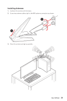
MSI MEG Z490 ACE User Manual - Page 27
Component Contents, Port Name, Port Type
 |
View all MSI MEG Z490 ACE manuals
Add to My Manuals
Save this manual to your list of manuals |
Page 27 highlights
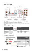
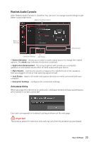
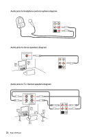
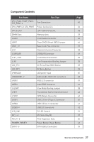
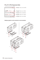
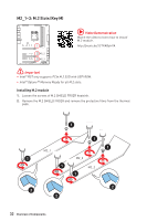
Component Contents Port Name CPU_FAN1, PUMP_FAN1, SYS_FAN1~6 CPU_PWR1~2, ATX_PWR1 CPU Socket DIMM Slots JAUD1 JBAT1 JBLK_U1 JCI1 JCORSAIR1 JFP1, JFP2 JLN1 JOC_FS1 JOC_RT1 JPWRLED1 JRAINBOW1~2 JRGB1 JRTD3 JSLOW1 JTBT1 JTPM1 JUSB1 JUSB2 JUSB3~4 LED_SW1 M2_1~3 PCI_E1~5 POWER1, RESET1 SATA1~6 Port Type Fan Connectors Power Connectors LGA 1200 CPU Socket Memory slots Front Audio Connector Clear CMOS (Reset BIOS) Jumper Base clock Plus connector Chassis Intrusion Connector CORSAIR Connector Front Panel Connectors Low Temperature Booting Jumper OC Force Enter BIOS Button OC Retry Button LED power input Addressable RGB LED connectors RGB LED connector Intel RTD3 Connector Slow Mode Booting Jumper Thunderbolt Add-on Card Connector TPM Module Connector USB 3.2 Gen 2 Type-C Connector USB 3.2 Gen 1 Connector USB 2.0 Connectors EZ LED Control M.2 Slots (Key M) PCIe Expansion Slots Power Button, Reset Button SATA 6Gb/s Connectors Page 43 36 28 29 40 46 37 45 49 35 38 39 39 50 48 47 44 38 44 42 40 41 42 51 32 30 46 34 Overview of Components 27
-
 1
1 -
2
-
3
-
4
-
5
-
6
-
7
-
8
-
9
-
10
-
11
-
12
-
13
-
14
-
15
-
16
-
17
-
18
-
19
-
20
-
21
-
 22
22 -
 23
23 -
 24
24 -
 25
25 -
 26
26 -
 27
27 -
 28
28 -
 29
29 -
 30
30 -
 31
31 -
 32
32 -
33
-
34
-
35
-
36
-
37
-
38
-
39
-
40
-
41
-
42
-
43
-
44
-
45
-
46
-
47
-
48
-
49
-
50
-
51
-
52
-
53
-
54
-
55
-
56
-
57
-
58
-
59
-
60
-
61
-
62
-
63
-
64
-
65
-
66
-
67
-
68
-
69
-
70
-
71
-
72
-
73
-
74
-
75
-
76
-
77
-
78
-
79
-
80
-
81
-
82
-
83
-
84
-
85
-
86
-
87
-
88
-
89
-
90
-
91
-
92
-
93
 |
 |
