MSI MPG X570S CARBON MAX WIFI User Manual - Page 48
JPWRLED1: LED power input, EZ Debug LED, LED_SW1: EZ LED Control
 |
View all MSI MPG X570S CARBON MAX WIFI manuals
Add to My Manuals
Save this manual to your list of manuals |
Page 48 highlights
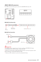
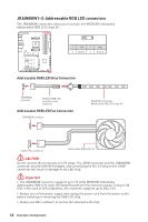
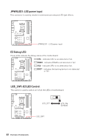
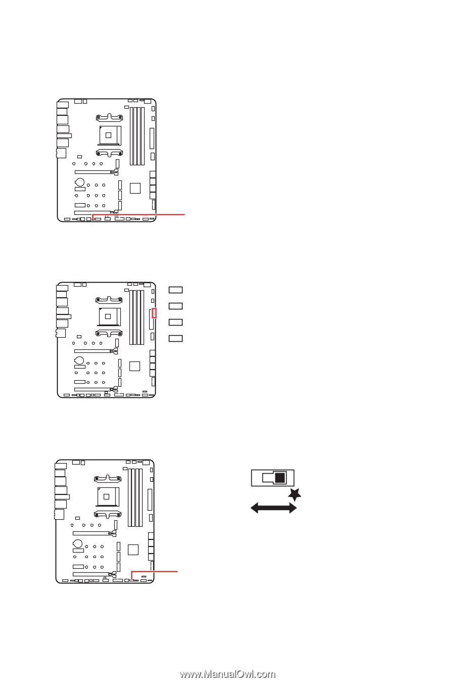
JPWRLED1: LED power input This connector is used by retailers to demonstrate onboard LED light effects. JPWRLED1 - LED power input EZ Debug LED These LEDs indicate the debug status of the motherboard. CPU - indicates CPU is not detected or fail. DRAM - indicates DRAM is not detected or fail. VGA - indicates GPU is not detected or fail. BOOT - indicates the booting device is not detected or fail. LED_SW1: EZ LED Control This switch is used to switch on/ off all the LEDs of motherboard. LED_OFF LED_SW1 LED_ON (Default) 48 Overview of Components
-
 1
1 -
2
-
3
-
4
-
5
-
6
-
7
-
8
-
9
-
10
-
11
-
12
-
13
-
14
-
15
-
16
-
17
-
18
-
19
-
20
-
21
-
22
-
23
-
24
-
25
-
26
-
27
-
28
-
29
-
30
-
31
-
32
-
33
-
34
-
35
-
36
-
37
-
38
-
39
-
40
-
41
-
42
-
 43
43 -
 44
44 -
 45
45 -
 46
46 -
 47
47 -
 48
48 -
 49
49 -
 50
50 -
 51
51 -
 52
52 -
 53
53 -
54
-
55
-
56
-
57
-
58
-
59
-
60
-
61
-
62
-
63
-
64
 |
 |
48
Overview of Components
EZ Debug LED
These LEDs indicate the debug status of the motherboard.
CPU
- indicates CPU is not detected or fail.
DRAM
- indicates DRAM is not detected or fail.
VGA
- indicates GPU is not detected or fail.
BOOT
- indicates the booting device is not detected
or fail.
JPWRLED1: LED power input
This connector is used by retailers to demonstrate onboard LED light effects.
JPWRLED1 - LED power input
LED_SW1: EZ LED Control
This switch is used to switch on/ off all the LEDs of motherboard.
LED_SW1
LED_OFF
LED_ON
(Default)