MSI MPG Z390 GAMING PRO CARBON User Manual - Page 43
Onboard LEDs, EZ Debug LED, DIMM LEDs, XMP LED, JPWRLED1: LED power input
 |
View all MSI MPG Z390 GAMING PRO CARBON manuals
Add to My Manuals
Save this manual to your list of manuals |
Page 43 highlights
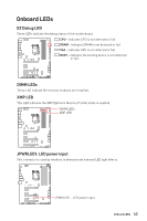
Onboard LEDs EZ Debug LED These LEDs indicate the debug status of the motherboard. CPU - indicates CPU is not detected or fail. DRAM - indicates DRAM is not detected or fail. VGA - indicates GPU is not detected or fail. BOOT - indicates the booting device is not detected or fail. DIMM LEDs These LED indicate the memory modules are installed. XMP LED This LED indicates the XMP (Extreme Memory Profile) mode is enabled. DIMM LEDs XMP LED JPWRLED1: LED power input This connector is used by retailers to demonstrate onboard LED light effects. JPWRLED1 - LED power input Onboard LEDs 43
-
 1
1 -
2
-
3
-
4
-
5
-
6
-
7
-
8
-
9
-
10
-
11
-
12
-
13
-
14
-
15
-
16
-
17
-
18
-
19
-
20
-
21
-
22
-
23
-
24
-
25
-
26
-
27
-
28
-
29
-
30
-
31
-
32
-
33
-
34
-
35
-
36
-
37
-
 38
38 -
 39
39 -
 40
40 -
 41
41 -
 42
42 -
 43
43 -
 44
44 -
 45
45 -
 46
46 -
 47
47 -
 48
48 -
49
-
50
-
51
-
52
-
53
-
54
-
55
-
56
-
57
-
58
-
59
-
60
-
61
-
62
-
63
-
64
-
65
-
66
-
67
-
68
-
69
-
70
-
71
-
72
-
73
-
74
-
75
-
76
-
77
-
78
-
79
-
80
-
81
-
82
-
83
-
84
-
85
-
86
-
87
-
88
 |
 |

43
Onboard LEDs
Onboard LEDs
EZ Debug LED
These LEDs indicate the debug status of the motherboard.
CPU
- indicates CPU is not detected or fail.
DRAM
- indicates DRAM is not detected or fail.
VGA
- indicates GPU is not detected or fail.
BOOT
- indicates the booting device is not detected
or fail.
DIMM LEDs
DIMM LEDs
These LED indicate the memory modules are installed.
XMP LED
This LED indicates the XMP (Extreme Memory Profile) mode is enabled.
XMP LED
JPWRLED1: LED power input
This connector is used by retailers to demonstrate onboard LED light effects.
JPWRLED1 - LED power input