MSI MS-6580-060 User Guide - Page 64
CAS# Latency, RAS# Precharge, Precharge Delay, Burst Length
 |
UPC - 816909002959
View all MSI MS-6580-060 manuals
Add to My Manuals
Save this manual to your list of manuals |
Page 64 highlights
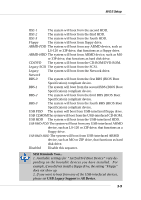
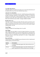
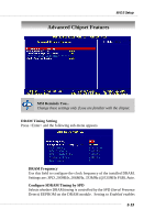
MS-6580 ATX Mainboard the following fields automatically to be determined by BIOS based on the configurations on the SPD. Selecting Disabled allows users to configure these fields manually. CAS# Latency This controls the timing delay (in clock cycles) before SDRAM starts a read command after receiving it. Settings: 2, 2.5 (clocks). 2 (clocks) increases the system performance the most while 2.5 (clocks) provides the most stable performance. RAS# Precharge This item controls the number of cycles for Row Address Strobe (RAS) to be allowed to precharge. If insufficient time is allowed for the RAS to accumulate its charge before DRAM refresh, refresh may be incomplete and DRAM may fail to retain data. This item applies only when synchronous DRAM is installed in the system. Available settings: 2 clocks, 3 clocks. RAS# to CAS# Delay When DRAM is refreshed, both rows and columns are addressed separately. This setup item allows you to determine the timing of the transition from RAS (row address strobe) to CAS (column address strobe). The less the clock cycles, the faster the DRAM performance. Setting options: 3 clocks, 2 clocks. Precharge Delay This setting controls the precharge delay, which determines the timing delay for DRAM precharge. Settings: 5 clocks, 6 clocks, 7 clocks. Burst Length This setting allows you to set the size of Burst-Length for DRAM. Bursting feature is a technique that DRAM itself predicts the address of the next memory location to be accessed after the first address is accessed. To use the feature, you need to define the burst length, which is the actual length of burst plus the starting address and allows internal address counter to properly generate the next memory location. The bigger the size, the faster the DRAM performance. Available settings: 4, 8. 3-14
-
 1
1 -
2
-
3
-
4
-
5
-
6
-
7
-
8
-
9
-
10
-
11
-
12
-
13
-
14
-
15
-
16
-
17
-
18
-
19
-
20
-
21
-
22
-
23
-
24
-
25
-
26
-
27
-
28
-
29
-
30
-
31
-
32
-
33
-
34
-
35
-
36
-
37
-
38
-
39
-
40
-
41
-
42
-
43
-
44
-
45
-
46
-
47
-
48
-
49
-
50
-
51
-
52
-
53
-
54
-
55
-
56
-
57
-
58
-
 59
59 -
 60
60 -
 61
61 -
 62
62 -
 63
63 -
 64
64 -
 65
65 -
 66
66 -
 67
67 -
 68
68 -
 69
69 -
70
-
71
-
72
-
73
-
74
-
75
-
76
-
77
-
78
-
79
-
80
-
81
-
82
-
83
-
84
-
85
-
86
-
87
-
88
-
89
-
90
-
91
-
92
-
93
-
94
-
95
-
96
-
97
-
98
-
99
-
100
-
101
-
102
-
103
-
104
-
105
-
106
-
107
 |
 |