MSI NX6600 User Guide - Page 24
Digital Panel Connector DVI-I, DVI-I Connector Pin Definition
 |
View all MSI NX6600 manuals
Add to My Manuals
Save this manual to your list of manuals |
Page 24 highlights
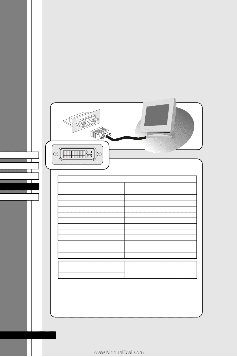
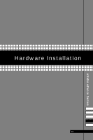
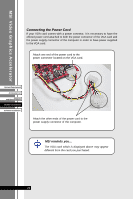
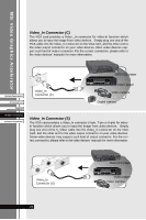
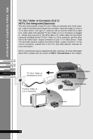
MSI Video Graphics Accelerator Digital Panel Connector (DVI-I) The VGA card provides a DVI (Digital Visual Interface) connector which allows you to connect an LCD monitor. The DVI connector provides a high-speed digital interconnection between the computer and its display device. To connect a LCD monitor, simply plug your monitor cable into the DVI connector on the VGA card, and make sure that the other end of the cable is properly connected to your monitor. (refer to your monitor manual for more information.) DVI connector System Requirement Accessory List Features and Specifications Hardware Installation Software Installation 1 8 LCD Monitor 17 24 DVI-I Connector Pin Definition DVI-I Connector Pin Signal Assignment 1 T.M.D.S.* Data22 T.M.D.S. Data2+ 3 T.M.D.S. Data2/4 Shield 4 T.M.D.S. Data45 T.M.D.S. Data4+ 6 DDC Clock 7 DDC Data 8 N/C 9 T.M.D.S. Data110 T.M.D.S. Data1+ 11 T.M.D.S. Data1/3 Shield 12 T.M.D.S. Data3- Pin Signal Assignment 13 T.M.D.S. Data3+ 14 +5V 15 GND (for +5V) 16 Hot Plug Detect 17 T.M.D.S. Data018 T.M.D.S. Data0+ 19 T.M.D.S. Data0/5 Shield 20 T.M.D.S. Data521 T.M.D.S. Data5+ 22 T.M.D.S. Clock Shield 23 T.M.D.S. Clock+ 24 T.M.D.S. Clock- C 1 Analog Red C 2 Analog Green C 3 Analog Blue C 4 Analog Horizontal Sync C 5 Analog Ground (analog R, G & B return *T.M.D.S. Technology The graphics data sent t o t he d igi tal moni tor use Transi tio n Mi nimized Differential Si gnali ng (T.M.D.S.)techn ology. TMDS uses an enco di ng algorith m to 8-bit s of da ta into a 10-bit transi ti on min imi xed , DC balanced charact er, which a re transi tio nmi nimized to reduce EMI wi th cop per cables an d DC-balanced for tran smi ssi on over fi ber optic cables. The TMDS a lg orit hm also p ro vid es robust clo ck reco very for greater skew t olerance wit h lo ng er cables o r lo w co st sho rt cables. 24
-
 1
1 -
2
-
3
-
4
-
5
-
6
-
7
-
8
-
9
-
10
-
11
-
12
-
13
-
14
-
15
-
16
-
17
-
18
-
 19
19 -
 20
20 -
 21
21 -
 22
22 -
 23
23 -
 24
24 -
 25
25 -
 26
26 -
 27
27 -
 28
28 -
 29
29 -
30
-
31
-
32
-
33
-
34
-
35
-
36
-
37
-
38
-
39
-
40
-
41
-
42
 |
 |