MSI P43 NEO-F User Guide
MSI P43 NEO-F - Motherboard - ATX Manual
 |
UPC - 816909045857
View all MSI P43 NEO-F manuals
Add to My Manuals
Save this manual to your list of manuals |
MSI P43 NEO-F manual content summary:
- MSI P43 NEO-F | User Guide - Page 1
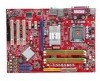
P45 Neo/ G45 Neo / P43 Neo Series MS-7519 (v1.X) Mainboard G52-75191X6 i - MSI P43 NEO-F | User Guide - Page 2
's manual, please contact your place of purchase or local distributor. Alternatively, please try the following help resources for further guidance. Visit the MSI website for FAQ, technical guide, BIOS updates, driver updates, and other information: http://global.msi.com.tw/index.php? func=service - MSI P43 NEO-F | User Guide - Page 3
instructions carefully. 2. Keep this User's Manual for future reference. 3. Keep this equipment away from humidity. 4. Lay this equipment on a reliable flat surface before setting it up. 5. The openings on the enclosure are for air convection hence protects equipment checked by service personnel: † - MSI P43 NEO-F | User Guide - Page 4
limits are designed to provide reasonable protection against harmful interference in a residential installation used in accordance with the instructions, may cause harmful interference D'INSTALLATIONAVANT DE RACCORDER AU RESEAU. Micro-Star International MS-7519 This device complies with Part 15 of - MSI P43 NEO-F | User Guide - Page 5
WEEE (Waste Electrical and Electronic Equipment) Statement v - MSI P43 NEO-F | User Guide - Page 6
vi - MSI P43 NEO-F | User Guide - Page 7
vii - MSI P43 NEO-F | User Guide - Page 8
Support ...ii Safety Instructions iii FCC-B Radio Frequency Interference Statement iv WEEE (Waste Electrical and Electronic Equipment) Statement v English ...En-1 Specifications ...En-2 Central Processing Unit: CPU En-5 Memory ...En-7 Connectors, Jumpers, Slots En-9 Back Panel ...En-15 BIOS - MSI P43 NEO-F | User Guide - Page 9
English P45 Neo/ G45 Neo / P43 Neo User's Guide English En-1 - MSI P43 NEO-F | User Guide - Page 10
MS-7519 Mainboard Specifications Processor Support - Intel® Core 2 Extreme, Core 2 Quad, Core 2 Duo, Pentium Dual- Core and Celeron Dual-Core processors in the LGA775 package - Intel® next generation 45 nm Multi-core CPU *(For the latest information about CPU, please visit http://global.msi.com .tw/ - MSI P43 NEO-F | User Guide - Page 11
intrusion connector - 1 SPDIF-out pinheader - 1 CD-in connector - 1 front audio pinheader - 1 TPM Module connector (optional) - 2 Hardware Overclock FSB jumpers (JB1 & JB2) TPM (optional) - Supports TPM Slots - 1 PCI Express x16 slot, supports up to PCI Express 2.0 x16 speed - 2 PCI Express x1 slots - MSI P43 NEO-F | User Guide - Page 12
, p.En-12 J1394_1, p.En-10 F DD 1 , p.En-9 JT PM 1, p.En-13 JBAT1, p.En-14 JUSB1~4, p.En-11 JFP1, p.En-10 JFP2, p.En-10 Quick Components Guide of P45 Neo/ G45 Neo/ P43 Neo Series (MS-7519 v1.X) Mainboard En-4 - MSI P43 NEO-F | User Guide - Page 13
first to ensure the safety of CPU. Overc l o cki ng This mainboard is designed to support overclocking. However, please make sure your components are able to tolerate such abnormal setting, while doing overclocking. Any attempt to operate beyond product specifications is not recommended. We do not - MSI P43 NEO-F | User Guide - Page 14
MS-7519 Mainboard CPU & Cooler Installation Procedures for Socket 775 1. The CPU socket has a plastic cap on it to protect the contact from damage. Before you have installed the CPU, always cover it to protect the CPU status in BIOS. 2. Whenever CPU is not installed, always protect your CPU socket - MSI P43 NEO-F | User Guide - Page 15
modules. For more information on compatible components, please visit http://global.msi.com. tw/index.php?func=testreport 64x2=128 pin 56x2=112 pin Dual-Channel Memory Population Rules In Dual-Channel mode, the memory modules can transmit and receive data with two data bus lines simultaneously - MSI P43 NEO-F | User Guide - Page 16
MS-7519 Mainboard Installing Memory Modules You can find the notch on the memory module and the volt on the DIMM slot. Follow the procedures below to install the m em ory m odule properly. 1. The memory module has only one notch on the center and will only fit in the right ori ent at i on. 2. Insert - MSI P43 NEO-F | User Guide - Page 17
Control SENSOR +1 2V GND English Connectors, Jumpers, Slots Fan Power Connectors: CPUFAN1/ SYSFAN1/ SYSFAN2 The fan power connectors support system cooling fan with +12V. The CPU FAN supports Smart FAN function. When connect the wire to the connectors, always take note that the red wire is the - MSI P43 NEO-F | User Guide - Page 18
MS-7519 Mainboard Serial ATA Connector: SATA1~6 This connector is a high-speed Serial for electrical connection to the front panel switches and LEDs. The JFP1 is compliant with Intel® Front Panel I/O Connectivity Design Guide. Power Power LED Switch Speaker JFP1 2 1 10 9 HDD Reset LED Switch - MSI P43 NEO-F | User Guide - Page 19
ission. SPDIF_out VCC GND SPDIF Bracket (Optional) Front Panel Audio Connector: JAUD1 This connector allows you to connect the front panel audio and is com pliant with Intel® Front Panel I/O Connectivity Design Guide. LINE out_L Front_JD LINE out_R MIC _R MIC _L 9 1 10 2 LINE out_JD - MSI P43 NEO-F | User Guide - Page 20
MS-7519 Mainboard CD-In Connector: JCD1 This connector is provided for external audio . To clear the warning, you must enter the BIOS utility and clear the record. 1 CINTRU 2 GND You may use the 20-pin ATX power supply as you like. If you'd like to use the 20-pin ATX power supply, please plug your - MSI P43 NEO-F | User Guide - Page 21
ATX 12V Power Connector (2x2-Pin): JPWR2 This 12V power connector is used to provide power to the CPU. 21 GND GND 12V 12V 43 TPM Module Connector: JTPM1 (optional) This connector connects to a TPM (Trusted Platform Module) module (optional). Please refer to the TPM security platform manual - MSI P43 NEO-F | User Guide - Page 22
MS-7519 Mainboard Clear CMOS Jumper: JBAT1 There is a CMOS RAM onboard that PCI (Peripheral Component Interconnect) Slot The PCI slot supports LAN card, SCSI card, USB card, and other add-on cards that comply with PCI specifications. Important When adding or removing expansion cards, make sure - MSI P43 NEO-F | User Guide - Page 23
/keyboard. PS/2 Mouse connector (Green/ 6-pin female) PS/2 Keyboard connector (Purple/ 6-pin female) Parallel Port A parallel port is a standard printer port that supports Enhanced Parallel Port (EPP) and Extended Capabilities Parallel Port (ECP) m ode. 13 1 (25-pin female connector) 25 14 - MSI P43 NEO-F | User Guide - Page 24
MS-7519 Mainboard 1394 Port The IEEE1394 port on the back panel provides connection to IEEE1394 devices. LAN The standard RJ-45 LAN jack is for connection to the Local Area Network (LAN). You can connect a network cable to it. LED Color Left Orange Green Right Orange LED State Off On (steady state - MSI P43 NEO-F | User Guide - Page 25
= AMI, W = AWARD, and P = PHOENIX. 2nd - 5th digit refers to the model number. 6th refers to the Chipset vender as A = AMD, I = Intel, V = VIA, N = Nvidia, U = ULi. 7th - 8th digit refers to the customer as MS = all standard customers. V1.0 refers to the BIOS version. 051508 refers to the date this - MSI P43 NEO-F | User Guide - Page 26
MS-7519 Mainboard Entering Setup Power on the computer and the system will start POST (Power sub-menu. If you want to return to the main menu, just press . General Help The BIOS setup program provides a General Help screen. You can call up this screen from any menu by simply pressing . - MSI P43 NEO-F | User Guide - Page 27
enter the sub-menu. Standard CMOS Features Use this menu for basic system configurations, such as time, date etc. Advanced BIOS Features Use this menu frequency/voltage control and overclocking. Load Fail-Safe Defaults Use this menu to load the default values set by the BIOS vendor for stable system - MSI P43 NEO-F | User Guide - Page 28
MS-7519 Mainboard W hen enter the BIOS : Select the Standard CMOS Features and press to enter the Standard CMOS Features-m BIOS Setup utility. Important The configuration above are for general use only. If you need the detailed settings of BIOS, please see the manual in English version on MSI - MSI P43 NEO-F | User Guide - Page 29
and to activate the device. Utility m enu - The Utility menu shows the software applications that the mainboard supports. W ebSite menu- The W ebSite menu shows the necessary websites. Important Please visit the MSI website to get the latest drivers and BIOS for better system performance. En-21 - MSI P43 NEO-F | User Guide - Page 30
Deutsch P45 Neo/ G45 Neo / P43 Neo Benutzerhandbuch Deutsch De-1 - MSI P43 NEO-F | User Guide - Page 31
MS-7519 Mainboard Spezifikationen Pr o z e s s o r e n - Intel® Core 2 Extreme, Core 2 Quad, Core 2 Duo, Pentium Dual- Core und Celeron Dual-Core Prozessoren für Sockel LGA775 - Intel® der nächsten Generation 45 nm Multi-Kern CPU *(W eitere CPU Informationen finden Sie unter http://global.msi.com . - MSI P43 NEO-F | User Guide - Page 32
(optional) - 1 Gehäusekontaktschalter Stiftleiste - 1 SPDIF-Ausgang Stiftleiste - 1 CD-Stiftleiste für Audio Eingang - 1 Audio Stiftleiste für Gehäuse Audio Ein-/ Ausgänge - 1 TPM Anschluss (optional) - 2 Hardware Overclock FSB jumpers (JB1 & JB2) TPM (optional) - Unterstützt TPM Schnittstellen - MSI P43 NEO-F | User Guide - Page 33
MS-7519 Mainboard Maus/ Tastatur, S.De-15 Parallel Port, S.De-15 1394 LAN, Port, S.De-16 S.De-16 Serial Port, VGA Port, S.De-15 S.De-15 L-In RS-Out L-Out CS-Out Mic SS-Out Audio Port, S.De-16 USB Port, S.De-16 JPWR2, S.De-13 CPU Neo/ G45 Neo/ P43 Neo Mainboard Series (MS-7519 v1.X) De-4 - MSI P43 NEO-F | User Guide - Page 34
Mainboard unterstützt Intel® Prozessoren und verwendet hierfür einen CPU Sockel mit der Bezeichnung Sockel-775, um das Einsetzen der CPU zu erleichtern. Verf das ATX Netzteil ausgeschaltet und der Netzstecker gezogen ist, um die Unversehrtheit der CPU zu gewährleisten. Übertakten Dieses Motherboard - MSI P43 NEO-F | User Guide - Page 35
MS-7519 Mainboard CPU & Kühler Einbau für Sockel 775 1. Der CPU-Sockel besitzt zum Schutz eine Plastikabdeckung. Lassen ist. Wichtig 1. Prüfen Sie die Status der CPU im BIOS. 2. Wenn keine CPU installiert ist, schützen Sie immer den CPU-Sockel durch die Plastikabdeckung. 3. Die Mainboard Fotos, die - MSI P43 NEO-F | User Guide - Page 36
einsetzen. W eitere fähige Komponenten Informationen finden Sie unter http://global.msi.com. tw/index.php?func=testreport Deutsch 64x2=128 Pin 56x2=112 DDR2 und DDR können nicht untereinander getauscht werden und der Standard DDR2 ist nicht rückwärtskompatibel, installieren Sie DDR2 Speichermodule - MSI P43 NEO-F | User Guide - Page 37
MS-7519 Mainboard Vorgehensweise beim Einbau von Speicher M odulen Können Sie die Kerbe auf dem Speichermodul und das Volt auf dem DIMM-Sockel finden. Folgen Sie die - MSI P43 NEO-F | User Guide - Page 38
GND Deutsch Anschlüsse, Steckbrücken und Slots Stromanschlüsse für Lüfter: CPUFAN1/ SYSFAN1/ SYSFAN2 Die Anschlüsseunterstützen aktive Systemlüfter mit + 12V. CPU FAN kann Smart FAN Funktion unterstützen. Wenn Sie den Anschluss herstellen, sollten Sie im mer darauf achten, dass der rote Draht der - MSI P43 NEO-F | User Guide - Page 39
MS-7519 Mainboard Serial ATA Anschluss: SATA1~6 Der Anschluss ist eine Hochgeschwindigkeits Anschluss der Schalter und LEDs des Frontpaneels. JFP1 erfüllt die Anforderungen des "Intel Front Panel I/O Connectivity Design Guide". Power Power LED Switch Speaker JFP1 2 1 10 9 HDD Reset LED Switch - MSI P43 NEO-F | User Guide - Page 40
Dieser Anschluss ermöglicht den Anschluss von Audioein- und -ausgängen eines Frontpanels. Der Anschluss entspricht den Richtlinien des " Intel® Front Panel I/O Connectivity Design Guide". LINE out_L Front_JD LINE out_R MIC _R MIC _L 9 1 10 2 LINE out_JD NC(No pin) MIC_JD Presence# Ground De - MSI P43 NEO-F | User Guide - Page 41
MS-7519 Mainboard CD- Eingang: arnung aus. Um die W arnmeldung zu löschen, muss das BIOS aufgerufen und die Aufzeichnung gelöscht werden. 1 CINTRU 2 GND . Sie können auch ein 20-Pin ATX Netzteil verwenden, wenn Sie m öchten. Wenn Sie ein 20-Pin ATX Netzteil einsetzen m öchten, stecken Sie bitte - MSI P43 NEO-F | User Guide - Page 42
Deutsch ATX 12V Stromanschluss (2x2-Pin): JPWR2 Dieser 12V Stromanschluss wird verwendet, um die CPU mit Strom zu versorgen. 21 GND GND 12V 12V 43 TPM Modul dem Startvorgang ab. Setzen Sie bitte in diesem Fall das BIOS des Mainboards per Jumper in die Werkeinstellungen zuruck. De-13 - MSI P43 NEO-F | User Guide - Page 43
MS-7519 Mainboard Steckbrücke zur CMOS- Löschung: JBAT1 Auf Slot PCI (Peripheral Component Interconnect) Slot Die PCI Steckplätze unterstützt LAN Karte, SCSI Karte, USB Karte und andere Zusatzkarten cards,die mit PCI Spezifikationen , sei es an Steckbrücken ("Jumpern"), Schaltern oder im BIOS. De-14 - MSI P43 NEO-F | User Guide - Page 44
. PS/2 Mausanschluss (Grün/ 6-Pin Buchse) PS/2 Tastaturanschluss (Lila/ 6-Pin Buchse) Parallele Schnittstelle Die Parallele Schnittstelle ist eine Standard Druckerschnittstelle, die ebenso als Enhanced Parallel Port (EPP) und als Extended Capabilities Parallel Port (ECP) betrieben werden kann. 13 - MSI P43 NEO-F | User Guide - Page 45
MS-7519 Mainboard 1394 Port Das IEEE 1394 Port auf der hintere Anschlusspanel zu den Vorrichtungen IEEE1394. LAN Die Standard RJ-45 Buchse ist für Anschlus zum an ein Lokales Netzwerk (Local Area Network - LAN). Hier kann ein Netzwerkkabel angeschlossen werden. LED Farbe Links Orange Grün Rechts - MSI P43 NEO-F | User Guide - Page 46
- 5te Stelle bezeichnet die Modelnummer. 6te Stelle bezeichnet den Chipsatzhersteller, A = AMD, I = Intel, V = VIA, N = Nvidia, U = ULi. 7te - 8te Stelle bezieht sich auf den Kunden, MS=alle Standardkunden. V1.0 bezieht sich auf die BIOS Version. 051508 bezeichnet das Datum der Veröffentlichung des - MSI P43 NEO-F | User Guide - Page 47
MS-7519 Mainboard Aufruf des BIOS Setups Nach dem Einsc halten beginnt der Com puter den POST . Durch Drücken von kom men Sie zurück ins Hauptm enü. Allgemeine Hilfe Das BIOS Setup verfügt über eine Allgem eine Hilfe (General Help). Sie können diese aus jedem Menü einfach durch Dr - MSI P43 NEO-F | User Guide - Page 48
und drücken Sie die Eingabetaste (), um ein Unterm enü aufzurufen. Standard CMOS Features In diesem Menü können Sie die Basiskonfiguration Ihres Systems anpassen, so z.B. Uhrzeit, Datum usw. Advanced BIOS Features Verwenden Sie diesen Menüpunkt, um weitergehende Einstellungen an Ihrem System - MSI P43 NEO-F | User Guide - Page 49
MS-7519 Mainboard W enn hereinkommen Sie, gründen das BIOS Dienstprogramm, folgen Sie den Prozessen unten für die Standard Einstellungen für ein optimales System zu laden. 2. Einstellung Datum/ Zeit : W ählen Sie die "Standard-CMOS Eigenschaften" vor und betätigen Sie um das Standard-CMOS - MSI P43 NEO-F | User Guide - Page 50
. Gebrauchsmenmenü - das Gebrauchsmenü zeigt die SoftwareAnwendungen das die mainboard Unterstützungen. W ebSite Menü - das W ebsite Menü zeigt die notwendigen W ebsite. Wichtig Besichtigen Sie bitte die MSI Website, um die neuesten Treiber und BIOS für bessere System Leistung zu erhalten. De-21 - MSI P43 NEO-F | User Guide - Page 51
Français P45 Neo/ G45 Neo / P43 Neo Guide d'utilisation Français Fr-1 - MSI P43 NEO-F | User Guide - Page 52
Carte mère MS-7519 Spécifications Processeurs Supportés - Processeurs Intel® Core 2 Extreme, Core 2 Quad, Core 2 Duo, Pentium Dual-Core et Celeron Dual-Core dans le paquet LGA775 - Supporte la prochaine génération de CPU Intel® Multi-core en 45nm (Pour les dernières informations sur le CPU, veuillez - MSI P43 NEO-F | User Guide - Page 53
intrusion - 1 connecteur SPDIF-out - 1 connecteur CD-in - 1 connecteur audio avant - 1 connecteur TPM Module (optionnel) - 2 cavaliers Hardware Overclock FSB (JB1 et JB2) TPM (optionnel) - Supporte TPM Slots - 1 slot PCI Express x16, supporte la vitesse jusqu'à PCI Express 2.0 x1 6 - 2 slots PCI - MSI P43 NEO-F | User Guide - Page 54
-11 JCD1, p.Fr-12 J1394_1, p.Fr-10 F DD 1 , p.Fr-9 JT PM 1, p.Fr-13 JBAT1, p.Fr-14 JUSB1~4, p.Fr-11 JFP1, p.Fr-10 JFP2, p.Fr-10 Guide des composants des séries P45 Neo/ G45 Neo/ P43 Neo Carte mère(MS-7519 v1.X) Fr-4 - MSI P43 NEO-F | User Guide - Page 55
(CPU) La carte mère supporte les processeurs Intel®. Le socket 775 perm et une installation facile du CPU. Assurez ATX ou par débrancher le cordon d'alimentation de la prise mise à la terre pour garantir la sécurité de l'unité centrale. Overc l o cki ng Cette carte mère supporte l'overclocking - MSI P43 NEO-F | User Guide - Page 56
MS-7519 Installation du CPU et son ventilateur pour Socket 775 1. Le socket CPU possède un plastique de protection. Ne le retirer qu'au moment d'installer le CPU du CPU dans le BIOS. 2. Quand le CPU n'est pas installé, toujours protectez votre pin du socket CPU avec le plastique de protection pour - MSI P43 NEO-F | User Guide - Page 57
mémoire. Pour plus d'informations sur les composants compatibles, veuillez visiter http://global. ms i.c o m.t w/in dex .php ?fu nc =t es t repo rt Fran modules de mémorie DDR2 ne sont pas interchangeables avec DDR et le standard de DDR2 n'est pas compatible à l'envers. Il faut toujours installer - MSI P43 NEO-F | User Guide - Page 58
Carte mère MS-7519 Installation des modules de mémorie Vous pouvez trouvez l'encoche sur le module de mémoire et le volt sur le slot de DIMM. Suivez les procé - MSI P43 NEO-F | User Guide - Page 59
courant du ventilateur supportent le ventilateur de refroidissement du système avec +12V. Le ventilateur du CPU supporte la fonction de Smart Smart Fan (ventilation intelligente) dans l'utilitaire de configuration du BIOS pour contrōler automatiquement la vitesse du ventilateur processeur en - MSI P43 NEO-F | User Guide - Page 60
mère MS-7519 Connecteur Serial . Il est conforme au guide de conception de la connectivité Entrée/sortie du panneau avant Intel®. Power Power LED Switch un appareil IEEE1394 via un support optionnel IEEE1394. TPAGround TPBCablepower Ground 2 10 1 9 Support IEEE1394t (Optionnel) TPA+ Ground - MSI P43 NEO-F | User Guide - Page 61
numérique. SPDIF_out VCC GND Support SPDIF (Optionnel) Connecteur audio du panneau avant : JAUD1 Ce connecteur vous permet de relier les appareils audio au panneau avant, il est conforme au guide de conception de la connectivité Entrée/sortie du panneau avant Intel®. LINE out_L Front_JD LINE - MSI P43 NEO-F | User Guide - Page 62
re MS-7519 Connecteur CD-In : JCD1 Ce connecteur est fournit pour un audio externe ce message d'alerte, vous devez entrer dans le BIOS et désactiver l'alerte. 1 CINTRU 2 GND Attachement le pin 1 et le pin 13 si vous voulez utiliser l'alimentation ATX 20-pin. 12 24 +3.3V GND +12V +5V +12V +5V - MSI P43 NEO-F | User Guide - Page 63
Connecteur d'alimentation ATX 12V (2x2-Pin) : JPWR2 Le connecteur d'alim entation 12V est utilisé pour alimenter le CPU. 21 GND GND Vous pouvez overclocker le FSB afin d'augm enter la fréquence du processeur par le changement des cavaliers JB1 et JB2. Suivez les instructions suivantes pour - MSI P43 NEO-F | User Guide - Page 64
Carte mère MS-7519 Cavalier d'effacement du CMOS : JBAT1 Il y a un Slot PCI Express x 1 Slot PCI (Peripheral Component Interconnect) Les slots PCI supportent les cartes LAN, les cartes SCSI, les cartes USB, et les autres cartes d'ajout conformes , les interrupteurs ou la configuration BIOS. Fr-14 - MSI P43 NEO-F | User Guide - Page 65
/2 (Vert/ 6-pin féminin) Connecteur de clavier de PS/2 (Violet/ 6-pin féminin) Port Parallèle Un port parallèle est un port standard d'im prim ante qui supporte les modes Enhanced Parallel Port (EPP) et Extended Capabilities Parallel Port (ECP). 13 1 (Connecteur féminin de 25-pin) 25 14 Port - MSI P43 NEO-F | User Guide - Page 66
Carte mère MS-7519 Port 1394 Le port IEEE1394 sur le panneau arrière fournit une connexion aux périphériques IEEE1394. LAN La prise standard RJ-45 LAN sert à la connexion au réseau local (Local Area Network (LAN)). Vous pouvez y relier un câble de réseau. LED Couleur LED Statut Eteinte Gauche - MSI P43 NEO-F | User Guide - Page 67
le. Le sixième caractère se rapporte au jeu de puces : I = Intel, N = nVidia, et V = VIA. Les septième et huitième caractère se rapportent au client : MS = all standard customers (Tous les clients standard). V1.0 se rapporte à la version de BIOS. 051508 se rapporte à la date à laquelle est sortie ce - MSI P43 NEO-F | User Guide - Page 68
Carte mère MS-7519 Réglages d'Entrée Allum ez l'ordinateur et le systčm e lancera le souhaitez revenir au m enu principal, appuyez juste sur . Aide générale Le programm e de réglages BIOS fournit un écran d'aide générale. Vous pouvez faire sortir cet écran à partir de n'im porte quel m - MSI P43 NEO-F | User Guide - Page 69
sur pour accepter ou entrer dans le sous-m enu. Standard CMOS Features (Fonctions CMOS standard) Utilisez ce menu pour les configurations de système de base, com me l'heure, la date, etc. Advanced BIOS Features ( Fonctions BIOS avancées) Utilisez ce menu pour régler les objets des fonctions - MSI P43 NEO-F | User Guide - Page 70
MS-7519 Quand vous entrez dans l'unité de réglages BIOS BIOS pour un système m inimal plus stable. 2. Setup Date/ Time (Réglage de l'heure et de la date) : Choisissez Standard CMOS Features et appuyez sur afin d'entrer dans le menu Standard glages de quitter BIOS. Important Les configurations - MSI P43 NEO-F | User Guide - Page 71
le pilote/ Service du CD, qui le pop-up de l'écran pour accom plir l'installation. Le pilote/Service CD contient : Menu de pilote - Il m ontre les pilotes le souhaitez pour activer le dispositif. Menu de services - Il m ontre les applications logicielles supportées par la carte mère. Menu du - MSI P43 NEO-F | User Guide - Page 72
P45 Neo/ G45 Neo / P43 Neo Ru-1 - MSI P43 NEO-F | User Guide - Page 73
MS-7519 Intel® Core 2 Extreme, Core 2 Quad, Core 2 Duo, Pentium Dual-Core и Celeron Dual-Core LGA775 Intel® 45 nm CPU http://global.msi.com .tw/index.php?func=cpuform) FSB - 1600* (OC)/ 1333/ 1066/ 800 Intel® P45/ G45/ P43 Intel® ICH10 4 слота DDR2 DIMM DDR2 1066**/ 800/ 667 SDRAM - MSI P43 NEO-F | User Guide - Page 74
1394 1394 JMicron JMB381 FDD - 1 1 FDD с 360КБ, 720КБ, 1.2МБ, 1.44МБ и 2.88 1 PS/2 1 PS/2 1 1 1 порт VGA (для G45 4 порта USB 2.0 - 1 LAN - 6 1 порт 1394 4 USB 2.0 - 1 1394 1 1 SPDIF-out - 1 CD-in - 1 1 TPM 2 FSB (JB1 & JB2) TPM TPM 1 слот PCI Express x16 PCI - MSI P43 NEO-F | User Guide - Page 75
MS-7519 M ou se / Keyboard, p.Ru-15 Parallel Port, p.Ru-15 1394 LAN, Port, p.Ru-16 p.Ru-16 Serial Port, VGA Port, p.Ru-15 p.Ru-15 L-In RS-Out L-Out CS-Out Mic SS-Out Audio Port, p.Ru-16 USB Port, p.Ru-16 JPWR2, p.Ru-13 CPU JFP2, p.Ru-10 P45 Neo/ G45 Neo/ P43 Neo (MS-7519 v1.X) Ru-4 - MSI P43 NEO-F | User Guide - Page 76
CPU Intel Socket 775 CPU http://global.msi. com .tw/index.php?func=cpuform CPU CPU CPU CPU Ru-5 - MSI P43 NEO-F | User Guide - Page 77
MS-7519 Socket 775 1 2 3 4 5 6 7 alignment key 8 9 10 11 12 1 BIOS. 2 3 Ru-6 - MSI P43 NEO-F | User Guide - Page 78
Память DDR2: DIMM1~4 DIMM ht tp: //g lob al. ms i.c o m.t w/in dex .ph p?f unc =te s tr epo rt 64x2=128 pin 56x2=112 pin 2 1 DIMM1 DIMM2 DIMM3 DIMM4 2 DIMM1 DIMM2 DIMM3 DIMM4 Installed Empty DDR2 DDR DDR2 DDR2 DDR2. DIMM1. Ru-7 - MSI P43 NEO-F | User Guide - Page 79
MS-7519 DIMM 1 2 DIMM DIMM DIMM слоте. 3 DIMM Volt Notch Ru-8 - MSI P43 NEO-F | User Guide - Page 80
Control SENSOR +1 2V GND CPUFAN1/ SYSFAN1/ SYSFAN2 12V Smart FAN 12V GND CPUFAN1 SENSOR or NC +1 2V GND SYSFAN1/2 1 2. CPUFAN Dual Core Center. 3 CPUFAN 3 4 FDD: FDD1 FDD 360КБ, 720КБ, 1.2МБ, 1.44МБ или 2.88МБ. IDE: IDE1 IDE IDE. Master/ Slave Ru-9 - MSI P43 NEO-F | User Guide - Page 81
MS-7519 Serial ATA: SATA1~6 Serial ATA Serial ATA Serial ATA. Serial ATA JFP1, JFP2 JFP1 Intel® Front Panel I/O Connectivity Design Guide. Power Power LED Switch Speaker JFP1 2 1 10 9 HDD Reset LED Switch 2 1 8 7 JFP2 Power LED IEEE1394 Connector J1394_1 IEEE1394 - MSI P43 NEO-F | User Guide - Page 82
USB JUSB1~4 Intel® I/O Connectivity Design USB HDD MP3 10 9 USBOC Key (no pin) GND (Sony & Philips Digital Interconnect Format SPDIF_out VCC GND SPDIF Bracket JAUD1 I/O Connectivity Design Guide. LINE out_L Front_JD LINE out_R MIC _R MIC _L 9 1 10 2 LINE out_JD - MSI P43 NEO-F | User Guide - Page 83
MS-7519 CD-In: JCD1 R GND L JCI1 BIOS. 1 CINTRU 2 GND ATX 24 ATX: JPWR1 24 ATX 20 AT X 20 1 и 13. 12 24 +3.3V GND +12V +5V +12V +5V 5VSB +5V PWR OK NC GND GND +5V GND GND GND +5V PS-ON# GND +3.3V GND -12V +3.3V +3.3V 1 13 Ru-12 - MSI P43 NEO-F | User Guide - Page 84
ATX 12V (2x2-Pin): JPWR2 12 21 GND GND 12V 12V 43 РазъемTPM JTPM1 TPM (Trusted Platform Module TPM. LFRAME# LAD3 LAD2 LAD1 LAD0 LRST# LCLK - MSI P43 NEO-F | User Guide - Page 85
MS-7519 CMOS: JBAT1 CMOS CMOS CMOS 1 1 1 CMOS 2-3 1-2 CMOS Слот PCI Express (x16/ x1) Слот PCI Express PCI Express. Слот PCI Express x16 Слот PCI Express x1 Слот PCI (Peripheral Component Interconnect) Слот PCI LAN, SCSI, USB PCI. BIOS. Ru-14 - MSI P43 NEO-F | User Guide - Page 86
DIN PS/2 PS/2®. PS/2 6 PS/2 6 EPP ECP 13 1 (25 25 14 16550A с 16 FIFO 1 5 (9 6 9 VGA 15 DB 5 1 15 11 (15 DIN) Ru-15 - MSI P43 NEO-F | User Guide - Page 87
MS-7519 Порт 1394 Порт 1394 IEEE1394. LAN RJ-45 LAN LED Цвет Оранж. LED LAN LAN LAN. 10 100 1000 Мб/с. Порт USB Порт USB (Universal Serial Bus USB Выход Line CD Line MIC RS 4/ 5.1/ 7.1 CS 5.1/ 7.1 SS 7.1. Ru-16 - MSI P43 NEO-F | User Guide - Page 88
BIOS BIOS (BIOS SETUP BIOS SETUP 1 BIOS BIOS 2 BIOS A7519IMS V1.0 051508 где: 1 BIOS (A = AMI, W = AWARD, и P = PHOENIX 4 A = ATi, I = Intel, V = VIA, N = Nvidia, U = ULi 2 MS V1.0 BIOS. 051508 BIOS. Ru-17 - MSI P43 NEO-F | User Guide - Page 89
MS-7519 POST DEL Press DEL to enter SETUP RESET Ctrl>, , и . Main Menu Enter Esc >. F1 BIOS F1 ESC Ru-18 - MSI P43 NEO-F | User Guide - Page 90
от AMI® или AWARD Enter Standard CMOS Features CMOS Advanced BIOS Features BIOS BIOS. Integrated Peripherals Power Management Setup H/W Monitor BIOS Setting Password BIOS Cell Menu Cell Load Fail-Safe Defaults BIOS Load Optimized Defaults Save & Exit Setup CMOS Exit Without Saving - MSI P43 NEO-F | User Guide - Page 91
MS-7519 BIOS 1. Load Optimized Defaults Load Optimized Defaults Enter Ok 2. Setup Date/ Time Standard CMOS Features Enter 3. Save & Exit Setup Save & Exit Setup Enter Ok BIOS Setup. BIOS MSI. Ru-20 - MSI P43 NEO-F | User Guide - Page 92
CD Driver/Utility Driver/Utility Driver m enu Utility m enu W ebSite menu BIOS MSI. Ru-21
-
 1
1 -
 2
2 -
 3
3 -
 4
4 -
 5
5 -
 6
6 -
 7
7 -
8
-
9
-
10
-
11
-
12
-
13
-
14
-
15
-
16
-
17
-
18
-
19
-
20
-
21
-
22
-
23
-
24
-
25
-
26
-
27
-
28
-
29
-
30
-
31
-
32
-
33
-
34
-
35
-
36
-
37
-
38
-
39
-
40
-
41
-
42
-
43
-
44
-
45
-
46
-
47
-
48
-
49
-
50
-
51
-
52
-
53
-
54
-
55
-
56
-
57
-
58
-
59
-
60
-
61
-
62
-
63
-
64
-
65
-
66
-
67
-
68
-
69
-
70
-
71
-
72
-
73
-
74
-
75
-
76
-
77
-
78
-
79
-
80
-
81
-
82
-
83
-
84
-
85
-
86
-
87
-
88
-
89
-
90
-
91
-
92
 |
 |

MS-7519 (v1.X) Mainboard
G52-75191X6
P45 Neo/ G45 Neo
/ P43 Neo Series