MSI P45 NEO3-FR User Guide
MSI P45 NEO3-FR - Motherboard - ATX Manual
 |
UPC - 816909045659
View all MSI P45 NEO3-FR manuals
Add to My Manuals
Save this manual to your list of manuals |
MSI P45 NEO3-FR manual content summary:
- MSI P45 NEO3-FR | User Guide - Page 1
P45 Neo3/ G45 Neo3 / P43 Neo3 Series MS-7514 (v1.X) Mainboard G52-75141X6 i - MSI P45 NEO3-FR | User Guide - Page 2
's manual, please contact your place of purchase or local distributor. Alternatively, please try the following help resources for further guidance. Visit the MSI website for FAQ, technical guide, BIOS updates, driver updates, and other information: http://global.msi.com.tw/index.php? func=service - MSI P45 NEO3-FR | User Guide - Page 3
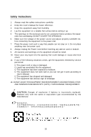
1. Always read the safety instructions carefully. 2. Keep this User's Manual for future reference. 3. Keep this equipment k . 11. If any of the following situations arises, get the equipment checked by service personnel: † The power cord or plug is damaged. † Liquid has penetrated into the - MSI P45 NEO3-FR | User Guide - Page 4
if not installed and used in accordance with the instructions, may cause harmful interference to radio communications. However, limits. VOIR LANOTICE D'INSTALLATIONAVANT DE RACCORDER AU RESEAU. Micro-Star International MS-7514 This device complies with Part 15 of the FCC Rules. Operation is subject - MSI P45 NEO3-FR | User Guide - Page 5
WEEE (Waste Electrical and Electronic Equipment) Statement v - MSI P45 NEO3-FR | User Guide - Page 6
vi - MSI P45 NEO3-FR | User Guide - Page 7
vii - MSI P45 NEO3-FR | User Guide - Page 8
Support ...ii Safety Instructions iii FCC-B Radio Frequency Interference Statement iv WEEE (Waste Electrical and Electronic Equipment) Statement v English ...En-1 Specifications ...En-2 Central Processing Unit: CPU En-5 Memory ...En-7 Connectors, Jumpers, Slots En-9 Back Panel ...En-15 BIOS - MSI P45 NEO3-FR | User Guide - Page 9
English P45 Neo3/G45 Neo3 / P43 Neo3 User's Guide English En-1 - MSI P45 NEO3-FR | User Guide - Page 10
MS-7514 Mainboard Specifications Processor Support - Intel® Core 2 Extreme, Core 2 Quad, Core 2 Duo, Pentium Dual- Core and Celeron Dual-Core processors in the LGA775 package - Intel® next generation 45 nm Multi-core CPU *(For the latest information about CPU, please visit http://global.msi.com .tw/ - MSI P45 NEO3-FR | User Guide - Page 11
- 1 SPDIF-out pinheader - 1 CD-in connector - 1 front audio pinheader - 1 TPM Module connector (optional) - 2 Hardware Overclock FSB jumpers (JB1 & JB2) TPM (optional) - Supports TPM Slots - 1 PCI Express x16 slot, support up to PCI Express 2.0 x16 speed - 1 PCI Express x1 slot - 4 PCI slots - MSI P45 NEO3-FR | User Guide - Page 12
-9 JFP2, p.En-10 JCI1, p.En-12 SYSFAN1, p.En-9 JBAT1, p.En-14 SATA1~8, p.En-10 JTPM1, p.En -13 JUSB1~4, p.En-11 JFP1, p.En-10 Quick Components Guide of P45 Neo3/ G45 Neo3/ P43 Neo3 Series (MS-7514 v1.X) Mainboard En-4 - MSI P45 NEO3-FR | User Guide - Page 13
first to ensure the safety of CPU. Overc l o cki ng This mainboard is designed to support overclocking. However, please make sure your components are able to tolerate such abnormal setting, while doing overclocking. Any attempt to operate beyond product specifications is not recommended. We do not - MSI P45 NEO3-FR | User Guide - Page 14
MS-7514 Mainboard CPU & Cooler Installation Procedures for Socket 775 1. The CPU socket has a plastic cap on it to protect the contact from damage. Before you have installed the CPU, always cover it to protect the socket pin. 2. Remove the cap from lever hinge side. 3. The pins of socket reveal. - MSI P45 NEO3-FR | User Guide - Page 15
modules. For more information on compatible components, please visit http://global.msi.com. tw/index.php?func=testreport 64x2=128 pin 56x2=112 pin Dual-Channel Memory Population Rules In Dual-Channel mode, the memory modules can transmit and receive data with two data bus lines simultaneously - MSI P45 NEO3-FR | User Guide - Page 16
MS-7514 Mainboard Installing Memory Modules You can find the notch on the memory module and the volt on the DIMM slot. Follow the procedures below to install the m em ory m odule properly. 1. The memory module has only one notch on the center and will only fit in the right ori ent at i on. 2. Insert - MSI P45 NEO3-FR | User Guide - Page 17
Slots Fan Power Connectors: CPUFAN/ SYSFAN1/ SYSFAN2 The fan power connectors support system cooling fan with +12V. The CPU FAN supports Smart FAN function. When connect the wire to the connectors, always take IDE device's documentation supplied by the vendors for jumper setting instructions. En-9 - MSI P45 NEO3-FR | User Guide - Page 18
MS-7514 Mainboard Serial ATA Connector: SATA1~8 This connector is a high-speed Serial ATA electrical connection to the front panel switches and LEDs. The JFP1 is compliant with Intel® Front Panel I/O Connectivity Design Guide. Power Power LED Switch Speaker JFP1 2 1 10 9 HDD Reset LED Switch - MSI P45 NEO3-FR | User Guide - Page 19
Bracket (Optional) Front Panel Audio Connector: JAUD1 This connector allows you to connect the front panel audio and is com pliant with Intel® Front Panel I/O Connectivity Design Guide. LINE out_L Front_JD LINE out_R MIC _R MIC _L 9 1 10 2 LINE out_JD NC(No pin) MIC_JD Presence# Ground En-11 - MSI P45 NEO3-FR | User Guide - Page 20
MS-7514 Mainboard CD-In Connector: JCD1 This connector is provided for external audio input. status and show a warning message on the screen. To clear the warning, you must enter the BIOS utility and clear the record. 1 CINTRU 2 GND Power Supply Attachment Before inserting the power supply connector - MSI P45 NEO3-FR | User Guide - Page 21
to provide power to the CPU. 21 GND GND 12V Please refer to the TPM security platform manual for more details and usages. LFRAME# Overclock FSB Jumpers: JB1, JB2 (optional) You can overclock the FSB to increase the processor frequency by changing the jumpers JB1 and JB2. Follow the instructions - MSI P45 NEO3-FR | User Guide - Page 22
MS-7514 Mainboard Clear CMOS Jumper: JBAT1 There is a CMOS RAM onboard that has PCI (Peripheral Component Interconnect) Slot The PCI slot supports LAN card, SCSI card, USB card, and other add-on cards that comply with PCI specifications. Important When adding or removing expansion cards, make - MSI P45 NEO3-FR | User Guide - Page 23
/2 Mouse connector (Green/ 6-pin female) PS/2 Keyboard connector (Purple/ 6-pin female) Parallel Port A parallel port is a standard printer port that supports Enhanced Parallel Port (EPP) and Extended Capabilities Parallel Port (ECP) m ode. 13 1 (25-pin female connector) 25 14 Serial Port The - MSI P45 NEO3-FR | User Guide - Page 24
MS-7514 Mainboard 1394 Port The IEEE1394 port on the back panel provides connection to IEEE1394 devices. LAN The standard RJ-45 LAN jack is for connection to the Local Area Network (LAN). You can connect a network cable to it. LED Color Left Orange Green Right Orange LED State Off On (steady state - MSI P45 NEO3-FR | User Guide - Page 25
in this chapter are under continuous update for better system performance. Therefore, the description may be slightly different from the latest BIOS and should be held for reference only. 2.Upon boot-up, the 1st line appearing after the memory count is the BIOS version. It is usually in the format - MSI P45 NEO3-FR | User Guide - Page 26
MS-7514 Mainboard Entering Setup Power on the computer and the system will start POST (Power On -menu. If you want to return to the main menu, just press . General Help The BIOS setup program provides a General Help screen. You can call up this screen from any menu by simply pressing - MSI P45 NEO3-FR | User Guide - Page 27
frequency/voltage control and overclocking. USER SETTINGS Use this menu to save/ load your settings to/ from CMOS for BIOS. Load Fail-Safe the BIOS vendor for stable system perform ance. Load Optimized Defaults Use this menu to load the default values set by the mainboard manufacturer specifically - MSI P45 NEO3-FR | User Guide - Page 28
MS-7514 Mainboard W hen enter the BIOS Setup utility, follow the processes below for general use. 1. Load and exit BIOS Setup utility. Important The configuration above are for general use only. If you need the detailed settings of BIOS, please see the manual in English version on MSI website. En - MSI P45 NEO3-FR | User Guide - Page 29
and to activate the device. Utility m enu - The Utility menu shows the software applications that the mainboard supports. W ebSite menu- The W ebSite menu shows the necessary websites. Important Please visit the MSI website to get the latest drivers and BIOS for better system performance. En-21 - MSI P45 NEO3-FR | User Guide - Page 30
Deutsch P45 Neo3/G45 Neo3 / P43 Neo3 Benutzerhandbuch Deutsch De-1 - MSI P45 NEO3-FR | User Guide - Page 31
MS-7514 Mainboard Spezifikationen Pr o z e s s o r e n - Intel® Core 2 Extreme, Core 2 Quad, Core 2 Duo, Pentium Dual- Core und Celeron Dual-Core Prozessoren für Sockel LGA775 - Intel® der nächsten Generation 45 nm Multi-Kern CPU *(W eitere CPU Informationen finden Sie unter http://global.msi.com . - MSI P45 NEO3-FR | User Guide - Page 32
Deutsch 1394 (optional) - Unterstützt 1394 über JMicron JMB381 Diskette - 1 Disketten Anschluss - Unterstützt 1 Diskettenlaufwerk mit 360KB, 720KB, 1.2MB, 1.44MB und 2.88MB An s c h l ü s s e Hintere Ein-/ und Ausgänge - 1 PS/2 Mausanschluss - 1 PS/2 Tastaturanschluss - 1 Parallele Schnittstelle - - MSI P45 NEO3-FR | User Guide - Page 33
-10 JCI1, S.De-12 SYSFAN1, S.De-9 JBAT1, S.De-14 SATA1~8, S.De-10 JTPM1, S.De -13 JUSB1~4, S.De-11 JFP1, S.De-10 Übersicht der Eingenschaften der P45 Neo3/ G45 Neo3/ P43 Neo3 Mainboard Series (MS-7514 v1.X) De-4 - MSI P45 NEO3-FR | User Guide - Page 34
: CPU Das Mainboard unterstützt Intel® Prozessoren und verwendet hierfür einen CPU Sockel mit der Bezeichnung Sockel-775, um das Einsetzen der CPU zu Netzstecker gezogen ist, um die Unversehrtheit der CPU zu gewährleisten. Übertakten Dieses Motherboard wurde so entworfen, dass es Übertakten - MSI P45 NEO3-FR | User Guide - Page 35
MS-7514 Mainboard CPU & Kühler Einbau für Sockel 775 1. Der CPU-Sockel besitzt zum Schutz eine Plastikabdeckung. Prüfen Sie die Status der CPU im BIOS. 2. Wenn keine CPU installiert ist, schützen Sie immer den CPU-Sockel durch die Plastikabdeckung. 3. Die Mainboard Fotos, die in diesem Abschnitt - MSI P45 NEO3-FR | User Guide - Page 36
Speicher DDR2: DIMM1~4 Sie können die Speichermodul in die DIMM Slots einsetzen. W eitere fähige Komponenten Informationen finden Sie unter http://global.msi.com. tw/index.php?func=testreport Deutsch 64x2=128 Pin 56x2=112 Pin Dual-Channel Speicher Bevölkerung Richtlinien Im Dual-Channel Modus, - MSI P45 NEO3-FR | User Guide - Page 37
MS-7514 Mainboard Vorgehensweise beim Einbau von Speicher M odulen Können Sie die Kerbe auf dem Speichermodul und das Volt auf dem DIMM-Sockel finden. Folgen Sie die unten - MSI P45 NEO3-FR | User Guide - Page 38
SYSFAN1/ SYSFAN2 Die Anschlüsseunterstützen aktive Systemlüfter mit + 12V. CPU FAN kann Smart FAN Funktion unterstützen. Wenn Sie den Anschluss herstellen, ist der Erdkontakt und sollte mit GND verbunden werden. Ist Ihr Mainboard m it einem Chipsatz zur Überwachung der System hardware versehen, dann - MSI P45 NEO3-FR | User Guide - Page 39
MS-7514 Mainboard Serial ATA Anschluss: SATA1~8 Der Anschluss ist eine Hochgeschwindigkeits Anschluss der Schalter und LEDs des Frontpaneels. JFP1 erfüllt die Anforderungen des "Intel Front Panel I/O Connectiv- ity Design Guide". Power Power LED Switch Speaker JFP1 2 1 10 9 HDD Reset LED - MSI P45 NEO3-FR | User Guide - Page 40
Dieser Anschluss ermöglicht den Anschluss von Audioein- und -ausgängen eines Frontpanels. Der Anschluss entspricht den Richtlinien des " Intel® Front Panel I/O Connectivity Design Guide". LINE out_L Front_JD LINE out_R MIC _R MIC _L 9 1 10 2 LINE out_JD NC(No pin) MIC_JD Presence# Ground De - MSI P45 NEO3-FR | User Guide - Page 41
MS-7514 Mainboard CD- Eingang: JCD1 Dieser Anschluss wird für externen Audioeingang zur Verfügung gestellt. auf dem Bildschirm eine W arnung aus. Um die W arnmeldung zu löschen, muss das BIOS aufgerufen und die Aufzeichnung gelöscht werden. 1 CINTRU 2 GND Zusätzlicher Hinweis Stromversorgung Bevor - MSI P45 NEO3-FR | User Guide - Page 42
ATX 12V Stromanschluss (2x2-Pin): JPWR2 Dieser 12V Stromanschluss wird verwendet, um die CPU mit Strom zu versorgen. 21 GND GND 12V 12V 43 TPM Modul Anschluss: nach dem Startvorgang ab. Setzen Sie bitte in diesem Fall das BIOS des Mainboards per Jumper in die Werkeinstellungen zuruck. De-13 - MSI P45 NEO3-FR | User Guide - Page 43
MS-7514 Mainboard Steckbrücke zur CMOS- Löschung: JBAT1 Auf dem Mainboard gibt es einen sogenannten CMOS Speicher (RAM), der über eine Batterie gespeist wird und Hard - oder Softwareeinstellung für die Erweiterungskarte vorzunehmen, sei es an Steckbrücken ("Jumpern"), Schaltern oder im BIOS. De-14 - MSI P45 NEO3-FR | User Guide - Page 44
Deutsch Hinteres Anschlusspanel Maus-/Tastatur Die Standard PS/2® Maus/Tastatur Stecker Mini DIN ist für eine PS/2® Maus/Tastatur. PS/2 Mausanschluss (Grün/ 6-Pin Buchse) PS/2 Tastaturanschluss (Lila/ 6-Pin Buchse) Parallele Schnittstelle Die Parallele Schnittstelle ist eine Standard - MSI P45 NEO3-FR | User Guide - Page 45
MS-7514 Mainboard 1394 Port Das IEEE 1394 Port auf der hintere Anschlusspanel zu den Vorrichtungen IEEE1394. LAN Die Standard RJ-45 Buchse ist für Anschlus zum an ein Lokales Netzwerk (Local Area Network - LAN). Hier kann ein Netzwerkkabel angeschlossen werden. LED Farbe Links Orange Grün Rechts - MSI P45 NEO3-FR | User Guide - Page 46
bezeichnet die Modelnummer. 6te Stelle bezeichnet den Chipsatzhersteller, A = AMD, I = Intel, V = VIA, N = Nvidia, U = ULi. 7te - 8te Stelle bezieht sich auf den Kunden, MS=alle Standardkunden. V1.0 bezieht sich auf die BIOS Version. 051508 bezeichnet das Datum der Veröffentlichung des BIOS. De-17 - MSI P45 NEO3-FR | User Guide - Page 47
MS-7514 Mainboard Aufruf des BIOS Setups Nach dem Einsc halten beginnt der Com puter den POST . Durch Drücken von kom men Sie zurück ins Hauptm enü. Allgemeine Hilfe Das BIOS Setup verfügt über eine Allgem eine Hilfe (General Help). Sie können diese aus jedem Menü einfach durch Dr - MSI P45 NEO3-FR | User Guide - Page 48
aufzurufen. Standard CMOS Features In diesem Menü können Sie die Basiskonfiguration Ihres Systems anpassen, so z.B. Uhrzeit, Datum usw. Advanced BIOS Features Verwenden Sie diesen Menüpunkt, um weitergehende Einstellungen an Ihrem System vorzunehm en. Integrated Peripherals Verwenden Sie dieses Men - MSI P45 NEO3-FR | User Guide - Page 49
MS-7514 Mainboard W enn hereinkommen Sie, gründen das BIOS Dienstprogramm, folgen Sie den Prozessen unten für ) Einstellungen zu speichern und das BIOS Setup zu verlassen. Wichtig Die Konfiguration oben dienen nur generellen Zwecken. Wenn Sie detaillierte BIOS- Einstellungen benötigen, dann sehen - MSI P45 NEO3-FR | User Guide - Page 50
an. Gebrauchsmenmenü - das Gebrauchsmenü zeigt die SoftwareAnwendungen das die mainboard Unterstützungen. W ebSite Menü - das W ebsite Menü zeigt die notwendigen W ebsite. Wichtig Besichtigen Sie bitte die MSI Website, um die neuesten Treiber und BIOS für bessere System Leistung zu erhalten. De-21 - MSI P45 NEO3-FR | User Guide - Page 51
Français P45 Neo3/G45 Neo3 / P43 Neo3 Guide d'utilisation Français Fr-1 - MSI P45 NEO3-FR | User Guide - Page 52
le paquet LGA775 - Supporte la prochaine génération de CPU Intel® Multi-core en 45nm *(Pour les dernières informations sur le CPU, veuillez visiter http://global.msi.com .tw/index.php?func=cpuform) FSB Supporté - 1600*(OC)/ 1333/ 1066/ 800 MHz Chipset - North Bridge: Chipset Intel® P45/ G45/ P43 - MSI P45 NEO3-FR | User Guide - Page 53
1394 par JMicron JMB381 FDD - 1 port de disquette - Supporte 1 FDD avec 360KB, 720KB, 1.2MB, 1.44MB et 2.88MB Connecteurs Module (optionnel) - 2 cavaliers Hardware Overclock FSB (JB1 et JB2) TPM (optionnel) - Supporte TPM Slots - 1 slot PCI Express x16, supporte la vitesse jusqu'à PCI Express 2.0 x1 - MSI P45 NEO3-FR | User Guide - Page 54
p.Fr-12 SYSFAN1, p.Fr-9 JBAT1, p.Fr-14 SATA1~8, p.Fr-10 Slot PCI, p.Fr-14 JAUD1, JSP1, p.Fr-11 p.Fr-11 JCD1, p.Fr-12 J1394_1, p.Fr-10 F DD 1 , p.Fr-9 JFP2, p.Fr-10 JTPM1, p.Fr-13 JUSB1~4, p.Fr-11 JFP1, p.Fr-10 Guide des composants des séries P45 Neo3/ G45 Neo3/ P43 Neo3 Carte mère (MS-7514 - MSI P45 NEO3-FR | User Guide - Page 55
CPU) La carte mère supporte les processeurs Intel®. Le socket 775 perm et une installation facile du CPU sur le CPU, veuillez visiter http://global.msi.com.tw unité centrale. Overclocking Cette carte mère supporte l'overclocking. Néanmoins, veuillez anormales, lors d'overclocking. Tout envie d'op - MSI P45 NEO3-FR | User Guide - Page 56
MS-7514 Installation du CPU et son ventilateur pour Socket 775 1. Le socket CPU possède un plastique de protection. Ne le retirer qu'au moment d'installer le CPU Lisez le statut du CPU dans le BIOS. 2. Quand le CPU n'est pas installé, toujours protectez votre pin du socket CPU avec le plastique de - MSI P45 NEO3-FR | User Guide - Page 57
destinés à installer les modules de mémoire. Pour plus d'informations sur les composants compatibles, veuillez visiter http://global. ms i.c o m.t w/in dex .php ?fu nc =t es t repo rt Français 64x2=128 pin 56x2=112 du système, inserez toujours les modules de mémorie dans le DIMM1 d'abord. Fr-7 - MSI P45 NEO3-FR | User Guide - Page 58
Carte mère MS-7514 Installation des modules de mémorie Vous pouvez trouvez l'encoche sur le module de mémoire et le volt sur le slot de DIMM. le slot du DIMM. 3. Vérifiez manuellement si la barrette mémoire a été verrouillée en place par les clips du slot DIMM sur les côtés. Volt Encoche Fr-8 - MSI P45 NEO3-FR | User Guide - Page 59
supportent le ventilateur de refroidissement du système avec +12V. Le ventilateur du CPU supporte de l'unité centrale. CPU FAN SENSOR or NC +1 du BIOS pour FDD1 Ce connecteur supporte le lecteur de disquette de IDE1 Ce connecteur supporte les lecteurs de instructions de configurations des cavaliers - MSI P45 NEO3-FR | User Guide - Page 60
mère MS-7514 Connecteur . Il est conforme au guide de conception de la connectivité Entrée/sortie du panneau avant Intel®. Power Power LED Switch support optionnel IEEE1394. support IEEE1394 (Optionnel) TPAGround TPBCablepower Ground 2 10 1 9 TPA+ Ground TPB+ Cable power Key(no pin) Fr - MSI P45 NEO3-FR | User Guide - Page 61
aux spécifications Intel I/O Connectivity Design Guide, est idéal transmission audio numérique. SPDIF_out VCC GND support SPDIF (Optionnel) Connecteur audio du panneau avant il est conforme au guide de conception de la connectivité Entrée/sortie du panneau avant Intel®. LINE out_L Front_JD LINE - MSI P45 NEO3-FR | User Guide - Page 62
Carte mère MS-7514 Connecteur CD-In : JCD1 Ce connecteur est fournit pour un un écran d'alerte. Pour effacer ce message d'alerte, vous devez entrer dans le BIOS et désactiver l'alerte. 1 CINTRU 2 GND Attachement d'Alimentation d'Énergie : Avant d'ins # GND +3.3V GND -12V +3.3V +3.3V 1 13 Fr-12 - MSI P45 NEO3-FR | User Guide - Page 63
d'alim entation 12V est utilisé pour alimenter le CPU. 21 GND GND 12V 12V 43 Connecteur TPM Module overclocking du matériaux : JB1, JB2 (optionnel) Vous pouvez overclocker le FSB afin d'augm enter la fréquence du processeur par le changement des cavaliers JB1 et JB2. Suivez les instructions - MSI P45 NEO3-FR | User Guide - Page 64
Carte mère MS-7514 Cavalier d'effacement du CMOS : JBAT1 Il y a un cela endommagerait la carte mère. Slot PCI Express (x16/ x1) Le slot PCI Express supporte la carte d'extension de l'interface de PCI Express. Slot PCI Express x 16 Slot PCI , les interrupteurs ou la configuration BIOS. Fr-14 - MSI P45 NEO3-FR | User Guide - Page 65
6-pin féminin) Port Parallèle Un port parallèle est un port standard d'im prim ante qui supporte les modes Enhanced Parallel Port (EPP) et Extended Capabilities Parallel Port (ECP). 13 1 (Connecteur féminin est fournit pour le moniteur. 5 1 15 11 (DIN Connecteur féminin de 15-Pin) Fr-15 - MSI P45 NEO3-FR | User Guide - Page 66
Carte mère MS-7514 Port 1394 Le port IEEE1394 sur le panneau arrière fournit une connexion aux périphériques IEEE1394. LAN La prise standard RJ-45 LAN sert à la connexion au réseau local (Local Area Network (LAN en mode de canal 5.1/ 7.1. SS-Out (Gris) - Side-Surround Out en mode de canal 7.1. Fr-16 - MSI P45 NEO3-FR | User Guide - Page 67
sous chaque catégorie BIOS décrits dans ce chapitre soit légčrement différente du BIOS le plus récent, et ne Intel, N = nVidia, et V = VIA. Les septième et huitième caractère se rapportent au client : MS = all standard customers (Tous les clients standard). V1.0 se rapporte à la version de BIOS - MSI P45 NEO3-FR | User Guide - Page 68
Carte mère MS-7514 Réglages d'Entrée Allum ez l'ordi nateur et le au m enu principal, appuyez juste sur . Aide générale Le programm e de réglages BIOS fournit un écran d'aide générale. Vous pouvez faire sortir cet écran à partir de n'im porte sur pour quitter l'écran d'aide. Fr-18 - MSI P45 NEO3-FR | User Guide - Page 69
ce m enu pour définir vos réglages du contrôle de la fréquence/voltage et de l 'overc l oc ki ng . USER SETTINGS (Réglages d'utilisation) Utilisez ce menu pour conserver/charger vos réglages de/à CMOS pour le BIOS. Load Fail-Safe Defaults (Défauts de sécurité de chargement intégrée) Utilisez - MSI P45 NEO3-FR | User Guide - Page 70
mère MS-7514 Quand vous entrez dans l'unité de réglages BIOS, suivez [Ok] et appuyer sur Enter chargera les valeurs défauts de BIOS pour un système m inimal plus stable. 2. Setup Date/ configurations et l'unité de réglages de quitter BIOS. Important Les configurations précédantes ne sont que pour l' - MSI P45 NEO3-FR | User Guide - Page 71
le pilote/ Service du CD, qui le pop-up de l'écran pour accom plir l'installation. Le pilote/Service CD contient : Menu de pilote - Il m ontre les pilotes le souhaitez pour activer le dispositif. Menu de services - Il m ontre les applications logicielles supportées par la carte mère. Menu du - MSI P45 NEO3-FR | User Guide - Page 72
P45 Neo3/G45 Neo3 / P43 Neo3 Ru-1 - MSI P45 NEO3-FR | User Guide - Page 73
MS-7514 Intel® Core 2 Extreme, Core 2 Quad, Core 2 Duo, Pentium Dual-Core и Celeron Dual-Core LGA775 Intel® 45 nm CPU http://global.msi.com.tw/index.php?func=cpuform ) FSB - 1600*(OC)/ 1333/ 1066/ 800 Intel® P45/ G45/ P43 Intel® ICH10/ ICH10R 4 слота DDR2 DIMM DDR2 1066**(OC)/ 800/ - MSI P45 NEO3-FR | User Guide - Page 74
1394 1394 JMicron JMB381 FDD - 1 1 FDD с 360КБ, 720КБ, 1.2МБ, 1.44МБ и 2.88 1 PS/2 1 PS/2 1 1 1 порт VGA (для G45 4 порта USB 2.0 - 1 LAN - 6 1 порт 1394 4 USB 2.0 - 1 1394 1 1 SPDIF-out - 1 CD-in - 1 1 TPM 2 FSB (JB1 & JB2) TPM TPM 1 слот PCI Express x16 PCI - MSI P45 NEO3-FR | User Guide - Page 75
MS-7514 M ou se / Keyboard, p.Ru-15 Parallel Port, p.Ru-15 1394 LAN, Port, p.Ru-16 p.Ru-16 Serial Port, VGA Port, p.Ru-15 p.Ru-15 L-In RS-Out L-Out CS-Out Mic SS-Out Audio Port, p.Ru-16 USB Port, p.Ru-16 JPWR2, SYSFAN2, CPU , p.Ru-10 P45 Neo3/ G45 Neo3/ P43 Neo3 (MS-7514 v1.X) Ru-4 - MSI P45 NEO3-FR | User Guide - Page 76
CPU Intel Socket 775 CPU http://global.msi. com .tw/index.php?func=cpuform CPU CPU Ru-5 - MSI P45 NEO3-FR | User Guide - Page 77
MS-7514 Socket 775 1 2 3 4 5 6 7 alignment key 8 9 10 11 12 1 BIOS. 2 3 Ru-6 - MSI P45 NEO3-FR | User Guide - Page 78
Память DDR2: DIMM1~4 DIMM ht tp: //g lob al. ms i.c o m.t w/in dex .ph p?f unc =te s tr epo rt 64x2=128 pin 56x2=112 pin 2 1 DIMM1 DIMM2 DIMM3 DIMM4 2 DIMM1 DIMM2 DIMM3 DIMM4 Installed Empty DDR2 DDR DDR2 DDR2 DDR2. DIMM1. Ru-7 - MSI P45 NEO3-FR | User Guide - Page 79
MS-7514 DIMM 1 2 DIMM DIMM DIMM слоте. 3 DIMM Volt Notch Ru-8 - MSI P45 NEO3-FR | User Guide - Page 80
Control SENSOR +1 2V GND CPUFAN/ SYSFAN1/ SYSFAN2 12V Smart FAN 12V GND CPU FAN SENSOR or NC +1 2V GND SYS FAN 1 2. CPUFAN Dual Core Center. 3 CPUFAN 3 4 FDD: FDD1 FDD 360КБ, 720КБ, 1.2МБ, 1.44МБ или 2.88МБ. IDE: IDE1 IDE - MSI P45 NEO3-FR | User Guide - Page 81
MS-7514 Serial ATA: SATA1~8 Serial ATA Serial ATA Serial ATA. SATA6 SATA4 SATA2 SATA8 SATA5 SATA3 SATA1 SATA7 Serial ATA JFP1, JFP2 JFP1 Intel® Front Panel I/O Connectivity Design Guide. Power Power LED Switch Speaker JFP1 2 1 10 9 HDD Reset LED Switch 2 1 8 7 - MSI P45 NEO3-FR | User Guide - Page 82
Bracket VCC и GND S/PDIF-Out: JSP1 S/PDIF (Sony & Philips Digital Interconnect Format SPDIF_out VCC GND SPDIF Bracket JAUD1 Intel® Front Panel I/O Connectivity Design Guide. LINE out_L Front_JD LINE out_R MIC _R MIC _L 9 1 10 2 LINE out_JD NC(No pin) MIC_JD Presence - MSI P45 NEO3-FR | User Guide - Page 83
MS-7514 CD-In: JCD1 R GND L JCI1 BIOS. 1 CINTRU 2 GND ATX 24 ATX: JPWR1 24 ATX 20 AT X 20 1 и 13. 12 24 +3.3V GND +12V +5V +12V +5V 5VSB +5V PWR OK NC GND GND +5V GND GND GND +5V PS-ON# GND +3.3V GND -12V +3.3V +3.3V 1 13 Ru-12 - MSI P45 NEO3-FR | User Guide - Page 84
ATX 12V (2x2-конт): JPWR2 12 21 GND GND 12V 12V 43 РазъемTPM JTPM1 TPM (Trusted Platform Module TPM. LFRAME# LAD3 LAD2 LAD1 LAD0 LRST# LCLK 13 1 14 2 GND GND Key(no pin) VCC5 SIRQ VCC3 3Vdual / 3V_STB FSB: JB1, JB2 JB1 и JB2 FSB FSB. 1 JB1 1 JB2 1 3 1 3 JB1 - MSI P45 NEO3-FR | User Guide - Page 85
MS-7514 CMOS: JBAT1 CMOS CMOS CMOS 1 1 1 JBAT1 3 Keep Data 3 Clear Data CMOS 2-3 1-2 CMOS Слот PCI Express (x16/ x1) Слот PCI . PCI Express x 16 Slot PCI Express x 1 Slot Слот PCI (Peripheral Component Interconnect) Слот PCI LAN, SCSI, USB PCI. BIOS. Ru-14 - MSI P45 NEO3-FR | User Guide - Page 86
DIN PS/2 PS/2®. PS/2 6 PS/2 6 EPP ECP 13 1 (25 25 14 16550A с 16 FIFO 1 5 (9 6 9 VGA 15 DB 5 1 15 11 (15 DIN) Ru-15 - MSI P45 NEO3-FR | User Guide - Page 87
MS-7514 Порт 1394 Порт 1394 IEEE1394. LAN RJ-45 LAN LED Цвет Оранж. LED LAN LAN LAN. 10 100 1000 Мб/с. Порт USB Порт USB (Universal Serial Bus USB Выход Line Line 7.1, CD RS 4/ 5.1/ 7.1 CS 5.1/ 7.1 SS 7.1. Ru-16 - MSI P45 NEO3-FR | User Guide - Page 88
BIOS BIOS (BIOS SETUP BIOS SETUP 1 BIOS BIOS 2 BIOS A7514IMS V1.0 051508 где: 1 BIOS (A = AMI, W = AWARD, и P = PHOENIX 4 A = ATi, I = Intel, V = VIA, N = Nvidia, U = ULi 2 MS V1.0 BIOS. 051508 BIOS. Ru-17 - MSI P45 NEO3-FR | User Guide - Page 89
MS-7514 POST DEL Press DEL to enter SETUP RESET Ctrl>, , и . Main Menu Enter Esc >. F1 BIOS F1 ESC Ru-18 - MSI P45 NEO3-FR | User Guide - Page 90
Standard CMOS Features CMOS Advanced BIOS Features BIOS BIOS. Integrated Peripherals Power Management Setup H/W Monitor BIOS Setting Password BIOS Cell Menu Cell USER SETTINGS BIOS в/ из CMOS. Load Fail-Safe Defaults BIOS Load Optimized Defaults Save & Exit - MSI P45 NEO3-FR | User Guide - Page 91
MS-7514 BIOS 1. Load Optimized Defaults Load Optimized Defaults Enter Ok 2. Setup Date/ Time Standard CMOS Features Enter 3. Save & Exit Setup Save & Exit Setup Enter Ok BIOS Setup. BIOS MSI. Ru-20 - MSI P45 NEO3-FR | User Guide - Page 92
CD Driver/Utility Driver/Utility Driver m enu Utility m enu W ebSite menu BIOS MSI. Ru-21
-
 1
1 -
 2
2 -
 3
3 -
 4
4 -
 5
5 -
 6
6 -
 7
7 -
8
-
9
-
10
-
11
-
12
-
13
-
14
-
15
-
16
-
17
-
18
-
19
-
20
-
21
-
22
-
23
-
24
-
25
-
26
-
27
-
28
-
29
-
30
-
31
-
32
-
33
-
34
-
35
-
36
-
37
-
38
-
39
-
40
-
41
-
42
-
43
-
44
-
45
-
46
-
47
-
48
-
49
-
50
-
51
-
52
-
53
-
54
-
55
-
56
-
57
-
58
-
59
-
60
-
61
-
62
-
63
-
64
-
65
-
66
-
67
-
68
-
69
-
70
-
71
-
72
-
73
-
74
-
75
-
76
-
77
-
78
-
79
-
80
-
81
-
82
-
83
-
84
-
85
-
86
-
87
-
88
-
89
-
90
-
91
-
92
 |
 |

MS-7514 (v1.X) Mainboard
G52-75141X6
P45 Neo3/ G45 Neo3
/ P43 Neo3 Series