MSI P45 NEO3-FR User Guide - Page 18
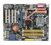
Ms-7514 Mainboard, Sata4, Sata3, Sata6, Sata2, Sata5, Sata1, Sata8, Sata7
 |
UPC - 816909045659
View all MSI P45 NEO3-FR manuals
Add to My Manuals
Save this manual to your list of manuals |
Page 18 highlights
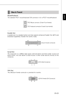
MS-7514 Mainboard Serial ATA Connector: SATA1~8 This connector is a high-speed Serial ATA interface port. Each connector can connect to one Serial ATA device. SATA6 SATA4 SATA2 SATA8 SATA5 SATA3 SATA1 SATA7 Important Please do not fold the Serial ATA cable into 90-degree angle. Otherwise, data loss may occur during transmission. Front Panel Connectors: JFP1, JFP2 These connectors are for electrical connection to the front panel switches and LEDs. The JFP1 is compliant with Intel® Front Panel I/O Connectivity Design Guide. Power Power LED Switch Speaker JFP1 2 1 10 9 HDD Reset LED Switch 2 1 8 7 JFP2 Power LED IEEE1394 Connector (Green): J1394_1 (optional) This connector allows you to connect the IEEE1394 device via an optional IEEE1394 brac ket . IEEE1394 Bracket (Optional) TPAGround TPBCablepower Ground 2 10 1 9 TPA+ Ground TPB+ Cable power Key(no pin) En-10
-
 1
1 -
2
-
3
-
4
-
5
-
6
-
7
-
8
-
9
-
10
-
11
-
12
-
 13
13 -
 14
14 -
 15
15 -
 16
16 -
 17
17 -
 18
18 -
 19
19 -
 20
20 -
 21
21 -
 22
22 -
 23
23 -
24
-
25
-
26
-
27
-
28
-
29
-
30
-
31
-
32
-
33
-
34
-
35
-
36
-
37
-
38
-
39
-
40
-
41
-
42
-
43
-
44
-
45
-
46
-
47
-
48
-
49
-
50
-
51
-
52
-
53
-
54
-
55
-
56
-
57
-
58
-
59
-
60
-
61
-
62
-
63
-
64
-
65
-
66
-
67
-
68
-
69
-
70
-
71
-
72
-
73
-
74
-
75
-
76
-
77
-
78
-
79
-
80
-
81
-
82
-
83
-
84
-
85
-
86
-
87
-
88
-
89
-
90
-
91
-
92
 |
 |
