MSI P45 NEO3-FR User Guide - Page 20
Power Supply Attachment, ATX 24-Pin Power Connector: JPWR1, CD-In Connector: JCD1, Chassis Intrusion
 |
UPC - 816909045659
View all MSI P45 NEO3-FR manuals
Add to My Manuals
Save this manual to your list of manuals |
Page 20 highlights
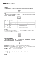
MS-7514 Mainboard CD-In Connector: JCD1 This connector is provided for external audio input. R GND L Chassis Intrusion Connector: JCI1 This connector connects to the chassis intrusion switch cable. If the chassis is opened, the chassis intrusion mechanism will be activated. The system will record this status and show a warning message on the screen. To clear the warning, you must enter the BIOS utility and clear the record. 1 CINTRU 2 GND Power Supply Attachment Before inserting the power supply connector, always make sure that all components are installed properly to ensure that no damage will be caused. All power connectors on the m ainboard have to connect to the ATX power supply and have to work together to ensure stable operation of the m ainboard. ATX 24-Pin Power Connector: JPWR1 This connector allows you to connect an ATX 24-pin power supply. To connect the ATX 24-pin power supply, make sure the plug of the power supply is inserted in the proper orientation and the pins are aligned. Then push down the power supply firmly into the c on nec t or . You may use the 20-pin ATX power supply as you like. If you'd like to use the 20-pin ATX power supply, please plug your power supply along with pin 1 & pin 13. 12 24 +3.3V GND +12V +5V +12V +5V 5VSB +5V PWR OK NC GND GND +5V GND GND GND +5V PS-ON# GND +3.3V GND -12V +3.3V +3.3V 1 13 En-12
-
 1
1 -
2
-
3
-
4
-
5
-
6
-
7
-
8
-
9
-
10
-
11
-
12
-
13
-
14
-
 15
15 -
 16
16 -
 17
17 -
 18
18 -
 19
19 -
 20
20 -
 21
21 -
 22
22 -
 23
23 -
 24
24 -
 25
25 -
26
-
27
-
28
-
29
-
30
-
31
-
32
-
33
-
34
-
35
-
36
-
37
-
38
-
39
-
40
-
41
-
42
-
43
-
44
-
45
-
46
-
47
-
48
-
49
-
50
-
51
-
52
-
53
-
54
-
55
-
56
-
57
-
58
-
59
-
60
-
61
-
62
-
63
-
64
-
65
-
66
-
67
-
68
-
69
-
70
-
71
-
72
-
73
-
74
-
75
-
76
-
77
-
78
-
79
-
80
-
81
-
82
-
83
-
84
-
85
-
86
-
87
-
88
-
89
-
90
-
91
-
92
 |
 |
